Electrical Machines: Unit I: a. Magnetic Circuits and Electromagnetism
Magnetic Hysteresis
Experimental Set up, Steps, Graph, Theory
Instead of plotting B-H curve only for increase in current if plotted for one complete cycle of magnetization (increase in current) and demagnetization (decrease in current) then it is called hysteresis curve or hysteresis loop.
Magnetic
Hysteresis
AU
: May-11
•
Earlier in chapter three we have studied B-H curve for a magnetic material.
Magnetic hysteresis is extension to the same concept of B-H curve.
•
Instead of plotting B-H curve only for increase in current if plotted for one
complete cycle of magnetization (increase in current) and demagnetization
(decrease in current) then it is called hysteresis curve or hysteresis loop.
•
Consider a circuit consisting of a battery 'E', an ammeter, variable resistance
R and reversible switch shown in the Fig. 1.16.1.
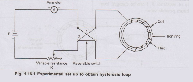
1. Steps in Obtaining Hysteresis Loop
i)
Initially variable resistance is kept maximum so current through the circuit is
very low. The field NI. strength H = NI/l is also very low. So as current is
increased, for low values of field strengths, flux density do not increase
rapidly. But after the knee point flux density increases rapidly upto certain
point. This point is called point of saturation. There-after any change in
current do not have an effect on the flux density. This curve is nothing but
the magnetization curve (B-H curve) discussed in earlier chapter. This is the initial
part of hysteresis loop.
ii)
After the saturation point, now current is again reduced to zero. Due to this
field strength also reduces to zero. But it is observed that flux density do
not trace the same curve back but falls back as compared to previous
magnetization curve. This phenomenon of falling back of flux density while
demagnetization cycle is called hysteresis. Hence due to this effect, when current
becomes exactly zero, there remains some magnetism associated with a coil and
hence the flux density. The core does not get completely demagnetized though
current through coil becomes zero. This value of flux density when exciting
current through the coil and magnetic field strength is reduced to zero is
called residual flux density or remanent flux density. This is also called
residual magnetism of the core. The magnitude of this residual flux or
magnetism depends on the nature of the material of the core. And this property
of the material is called retentivity
iii)
But now if it is required to demagnetize the core entirely then it is necessary
to reverse the direction of the current through the coil. This is possible with
the help of the intermediate switch.
Key Point :
The value of magnetic field strength required to wipe out the residual flux
density is called the coercive force. It is measured interms of coercivity.
iv)
If now this reversed current is increased, core will get saturated but in opposite
direction. At this point flux density is maximum but with opposite direction.
v)
If this current is reduced to zero, again core shows a hysteresis property and
does not get fully demagnetized. It shows same value of residual magnetism but
with opposite direction.
vi) If current is reversed again, then for a
certain magnitude of field strength, complete demagnetization of the core is
possible.
vii) And if it is increased further, then
saturation in the original direction is achieved completing one cycle of
magnetization and demagnetization.
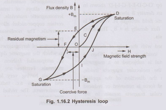
The curve plotted for such one cycle turns out
to be a closed loop which is called hysteresis loop. Its nature is shown in the
Fig. 1.16.2.
Part
of Curve Represents What?
O-C-D
:
Region corresponding to normal den magnetization curve increased form 'O' to
Imax corresponding to 'Bm Maximum flux density is + Bm
D-E
:
Current reduced to zero, but core cannot be completely demagnetized. O-E
represents residual magnetism and residual flux density, denoted by + Br
E-F
: Current
is reversed and increased in reversed direction to get complete demagnetization
of the core. C-F represent coercive force required to completely wipe out + Br
F-G
:
Current is increased in reversed direction till saturation in opposite
direction is achieved. Maximum flux density same but with opposite direction
i.e. – Bm
G-I
:
Current is reduced to zero but again flux density lags and core cannot be
completely demagnetized. O-I represents residual flux density in other
direction i.e. - Br
I-J
:
Current is again reversed and increased till complete demagnetization is
achieved.
J-D
:
Current is again increased in original direction till saturation is reached.
Corresponding flux density is again + Bm
2. Theory Behind Hysteresis Effect
•
As seen from the loop 'O-C-D-E-F-G-I-J-D' shown in the Fig. 1.16.2 the flux
density B always lags behind the values of magnetic field strength H. When H is
zero, corresponding flux density is + Br.This effect is known as hysteresis.
•
This can be explained with the help of theory of molecular magnets inside a
material. When a ferromagnetic material is subjected to a magnetic field
strength, all the molecular magnets inside, align themselves in the direction
of the applied m.m.f. If this applied force is removed or reduced some of the
molecular magnets remain in the aligned state and magnetic neutralization of
the material is not fully possible. So it continues to show some magnetic
properties which is defined as the residual magnetism.
•
The value of the residual magnetism as said earlier depends on the quality of
the magnetic material and the treatment it receives at the time of
manufacturing. This property is called as retentivity.
Key Point :
Higher the value of retentivity, higher the value of the power of the magnetic
material to retain its magnetism. For high retentivity, higher is the coercive
force required.
It
can be measured in terms coercivity of the material.
Review Question
1. What is magnetic
hysteresis ? Explain the hysteresis loop. AU
: May-11, Marks 4
Electrical Machines: Unit I: a. Magnetic Circuits and Electromagnetism : Tag: : Experimental Set up, Steps, Graph, Theory - Magnetic Hysteresis
Related Topics
Related Subjects

Electrical Machines I
EE3303 EM 1 3rd Semester EEE Dept | 2021 Regulation | 3rd Semester EEE Dept 2021 Regulation