Electrical Machines: Unit I: a. Magnetic Circuits and Electromagnetism
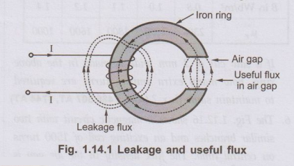
Magnetic Leakage and Fringing
Stacking factor =Net cross - sectional area occupied by magnetic material/Gross cross-sectional area
Magnetic
Leakage and Fringing
AU : May-10,15
•
Most of the applications which are using
magnetic effects of an electric current, are using flux in air gap for their
operation. Such devices are generators, motors, measuring instruments like
ammeter, voltmeter etc. Such devices consist of magnetic circuit with an air
gap and flux in air gap is used to produce the required effect.
•
Such flux which is available in air gap and is utilised to produce the desired
effect is called useful flux denoted by ϕu
•
It is expected that whatever is the flux produced by the magnetizing coil, it
should complete its path through the iron and air gap. So all the flux will be
available in air gap. In actual practice it is not possible to have entire flux
available in air gap. This is because, we have already seen that there is no
perfect insulator for the flux. So part of the flux completes its path through
the air or medium in which coil and magnetic circuit is placed.
Key Point :
Such flux which leaks and completes its path through surrounding air or medium
instead of the desired path is called the leakage flux.
The
Fig. 1.14.1 shows the useful and leakage flux.
1. Leakage Coefficient or Hopkinson's Coefficient
•
The ratio of the total flux (OT) to the useful flux (ou) is defined as the
leakage coefficient of Hopkinson's coefficient or leakage factor of that
magnetic circuit It is denoted by a λ.
ஃ λ
= Total flux / Useful flux = ϕT/ϕu
•
The value of ‘λ is always greater than 1
as ϕT is always more than ϕu.
It generally varies between 1.1 and 1.25. Ideally its value should be 1.
2. Magnetic Fringing
•
When flux enters into the air gap, it passes through the air gap in terms of
parallel flux lines. There exists a force of repulsion between the magnetic
lines of force which are parallel and having same direction. Due to this
repulsive force there is tendency of the magnetic flux to bulge out (spread
out) at the edge of the air gap. This tendency of flux to bulge out at the
edges of the air gap is called magnetic fringing.
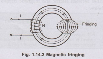
It has following two effects :
1)
It increases the effective cross-sectional area of the air gap.
2)
It reduces the flux density in the air gap.
So
leakage, fringing and reluctance, in practice should be as small as possible.
Key Point :
This is possible by choosing good magnetic material and making the air gap as
narrow as possible.
•
Practically if fringing effect is to be considered then the corrections for
short gaps are empirically made by adding one gap length to each of the two
dimensions making up its area.
• Thus if area of core is ac = lc
× lc, then the ag = ( lc + lg) × ( lc
+ lg) is the area of cross-section of air gap for considering
the effect of fringing. Thus ag > ac and the air gap
reluctance is less due to fringing.
• In case of circular cross-section while
calculating the area of cross-section for air gap the diameter is considered as
(d+2lg) where lg is the air gap length and d is the
diameter of cross-section of core. This takes into account the effect of
fringing.
3. Stacking Factor
•
Generally magnetic cores are made up of laminations which are lightly
insulated. The laminated construction helps to keep eddy current losses to low
value. Due to stacks of laminations, the net cross-sectional area occupied by
the magnetic material is less than its gross cross-sectional area. Thus the
stacking factor is defined as,
Stacking
factor =Net cross - sectional area occupied by magnetic material/Gross cross-sectional
area
As
gross cross-sectional area is higher, the stacking factor is always less than
unity.
Key Point : As the thickness of the laminations increases, the stacking factor approaches to unity.
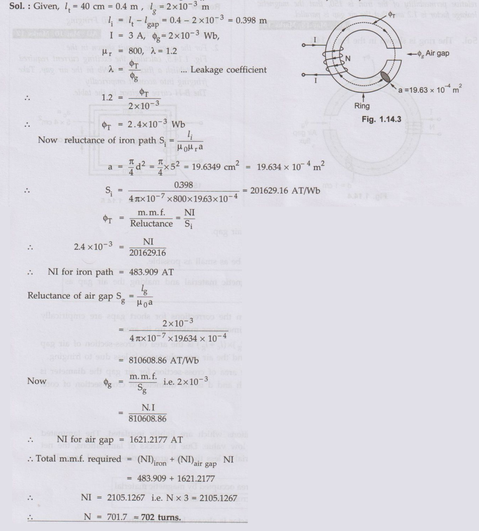
Ex. 1.14.1
A cast iron ring of 40 cm mean length and circular cross section of 5 cm
diameter is wound with a coil. The coil carries a current of 3 A and produces a
flux of 3 mWb in the air gap. The length of the air gap is 2 mm. The relative
permeability of the cast iron is 800. The leakage coefficient is 1.2. Calculate
number of turns of the coil.
Sol. :
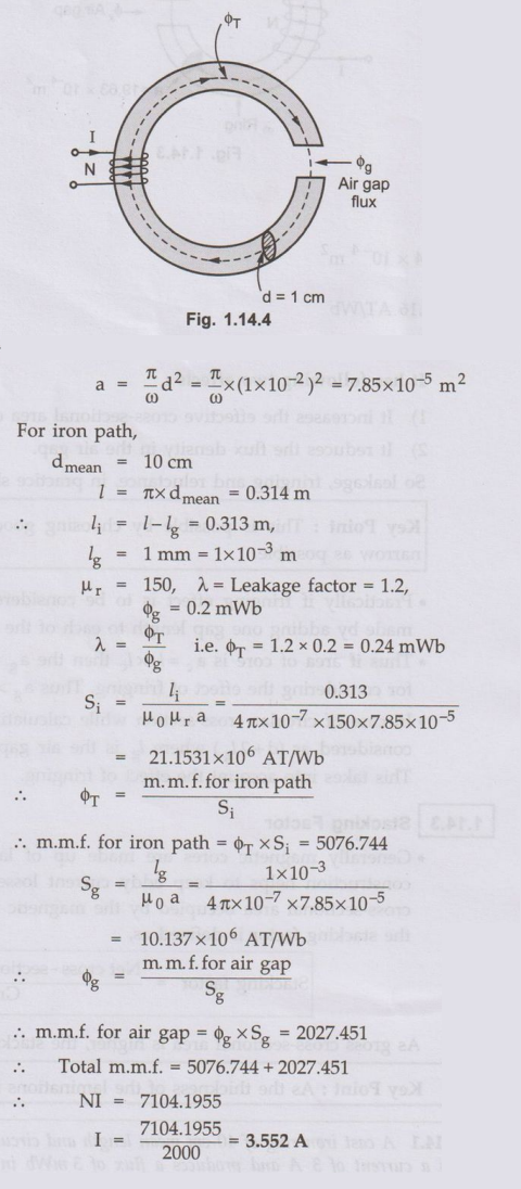
Ex. 1.14.2
The core of an electromagnet is made of an iron rod of 1 cm diameter, bent
in to a circle of mean diameter 10 cm, a radial air gap of 1 mm being left
between the ends of the rod. Calculate the direct current needed in coil of
2000 turns uniformly spaced around the core to produce a magnetic flux of 0.2
mWb in the air gap. Assume that the relative permeability of the iron is 150,
that the magnetic leakage factor is 1.2 and that the air gap is parallel. AU
: May-15, Marks 13
Sol. The ring is shown in
the Fig. 1.14.4.
Review Questions
1. Discuss : i)
Leakage flux ii) Fringing iii) Stacking factor. AU : May-10, Marks 12
2. For the magnetic circuit shown in the Fig.
1.14.5, calculate the exciting current required to establish a flux of 2 mWb in
the air gap. Take fringing into account empirically
The B-H curve is
given in the table.

Electrical Machines: Unit I: a. Magnetic Circuits and Electromagnetism : Tag: : - Magnetic Leakage and Fringing
Related Topics
Related Subjects

Electrical Machines I
EE3303 EM 1 3rd Semester EEE Dept | 2021 Regulation | 3rd Semester EEE Dept 2021 Regulation