Electromagnetic Theory: Unit III: (b) Magnetic Forces, Magnetic Materials and Inductance
Magnetic Torque and Magnetic Dipole Moment
with Example Solved Problems
• In the previous section we discussed the force on a current loop in a magnetic field. Let us now consider new quantity, magnetic torque.
Magnetic Torque and Magnetic Dipole Moment
AU
: Dec.-12,14,17, May-16,17,18,19
•
In the previous section we discussed the force on a current loop in a magnetic
field. Let us now consider new quantity, magnetic torque.
•
The moment of a force or torque about a specified point is defined as the
vector product of the moment arm ![]() and the force
and the force ![]() It is
measured in newton meter (Nm).
It is
measured in newton meter (Nm).


•
From above expression it is clear that when total force is zero, the torque is
independent of the choice of the origin.
1. Torque on a Planar Coil
•
Consider a differential current loop of rectangular shape with uniform magnetic
field everywhere around it as shown in the Fig. 8.5.3. Assume that the loop is
placed in xy-plane. Let the sides AB and CD be parallel to x-axis and sides BC
and DA be parallel to y-axis. Let dx and dy be the lengths of the sides of the
rectangular loop.

• Considering origin of the rectangular
co-ordinate system as the centre of the loop. The value of the magnetic field
at the centre of the rectangular loop carrying current I in anticlockwise
direction be BQ. As the rectangular loop is differential with the differential
lengths dx and dy, the value of the magnetic field can be assumed BQ
everywhere. The total force on the loop is zero and the origin for the torque
can be selected as the centre of the loop.
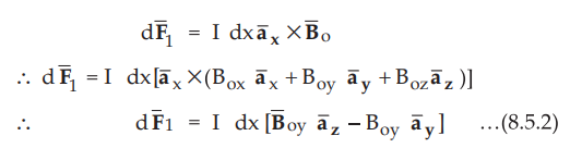
The
force exerted on side AB is given by,
For
the side AB, the level arm extends from origin to the midpoint of the side AB.
Thus the lever arm for side AB is given by,
 ...(8.5.3)
Hence
the torque on side 1 is given by,

•
For the side BC, the lever arm extends from origin to the midpoint of the side
BC. Thus the lever arm for side BC is given by,

•
For side CD, the torque contribution is exactly same as that by side AB. The
torque on side 3 is given by,

•
Similarly for DA, the torque contribution is exactly same as that by side BC.
The torque on side 4 is thus given by,

• Hence the total torque is given by,

•
We can modify above equation by replacing the product term i.e. dx dy by vector
area of the differential current loop i.e. ![]()

•
Above equation indicates that even though the total force exerted on the
rectangular loop as a whole is zero, the torque exists along the axis of
rotation, i.e. in the z-direction. The expression is valid for all the flat
loops of any arbitrary shape.
2. Magnetic Dipole Moment
•
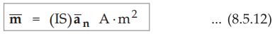
The magnetic dipole moment of a current loop is defined as the product of
current through the loop and the area of the loop, directed normal to the
current loop. From the definition it is clear that, the magnetic dipole moment
is a vector quantity. It is denoted by![]() . The direction of the magnetic
dipole moment
. The direction of the magnetic
dipole moment ![]() is given by the right hand thumb rule. The right hand
thumb indicates the direction of the unit vector in which
is given by the right hand thumb rule. The right hand
thumb indicates the direction of the unit vector in which ![]() is directed
and the figures represents the current direction. The magnetic dipole moment is
given by,
is directed
and the figures represents the current direction. The magnetic dipole moment is
given by,
•
In the previous section we have obtained the expression for the torque along
the axis of rotation of a planar coil as,

•
Using definition for the magnetic dipole moment, the torque can be expressed
as,

•
Above expression is in general applicable in calculating the overall torque on
a planar loop of any arbitrary shape. But the basic requirement is that the
magnetic field must be uniform. The torque is always in the direction of axis
of rotation. When the planar loop or coil is normal to the magnetic field, the
sum of the forces on the planar loop as well as the torque will be zero.
3. Magnetic Dipole
•
A magnetic dipole is nothing but a bar magnet or the filamentary current loop.
Consider small filamentary loop carrying current I as shown in the Fig. 8.5.4.

•
Let the infinitesimal current element be ![]() carrying current I. The
point P is at a distance r from the loop of radius a. Assume that distance r
between loop and point of observation to be very large as campared to the
radius of loop i.e. a.
carrying current I. The
point P is at a distance r from the loop of radius a. Assume that distance r
between loop and point of observation to be very large as campared to the
radius of loop i.e. a.
•
The vector magnetic potential at point P differential current element is given
by,

•
As per the assumption r >> a, the loop appears very small at point P. Such that,
Ā has only ϕ component,

It
is called magnetic moment of the loop.

•
It is observed that the expressions obtained for Ā and ![]() are very much
similar to those obtained for V and
are very much
similar to those obtained for V and ![]() in case of electric dipole. Thus we can
consider a small current loop as a magnetic dipole.
in case of electric dipole. Thus we can
consider a small current loop as a magnetic dipole.
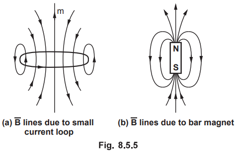
•
The ![]() lines are shown around the small current loop i.e a magnetic dipole
lines are shown around the small current loop i.e a magnetic dipole  . It is also observed that the
 ![]() lines due to a bar magnet are
very similar to the
lines due to a bar magnet are
very similar to the ![]() lines due to a small current loop. The
lines due to a small current loop. The ![]() lines due to a bar magnet are a shown in the Fig. 8.5.5 (b). Suppose Qm
is the isolated magnetic charge which exists in association with - Qm always.
When a bar of length I is placed in a uniform magnetic field
lines due to a bar magnet are a shown in the Fig. 8.5.5 (b). Suppose Qm
is the isolated magnetic charge which exists in association with - Qm always.
When a bar of length I is placed in a uniform magnetic field ![]() , a torque
is produced on bar given by,
, a torque
is produced on bar given by,

•
Note that the direction of ![]() is always from south to north as
represented in Fig. 8.5.5 (b).
is always from south to north as
represented in Fig. 8.5.5 (b).
This
torque produced aligns the bar with an external magnetic field. So the force
acting on the charge is given by,

•
Suppose in a given field ![]() , the torque produced by a small current
loop and a bar magnet is same, then they are equivalent of each other.
, the torque produced by a small current
loop and a bar magnet is same, then they are equivalent of each other.

•
Equation (8.5.19) represents the condition that the dipole moment of a small
current loop and a bar magnet must be same if they produce same torque in an
uniform magnetic field ![]() .
.
Ex.
8.5.1 Find the magnetic field due to a small circular loop of radius a carrying
current I, at a distance R from the loop. R is very large as compared to
dimensions of the loop as show in the Fig. 8.5.6.
Sol.
:
According to Biot-Savart law, the vector magnetic potential Ā at a distance r.
From the differential current element dL carrying current I is given by,

It
is given that distance R is very large compared to the radius of loop a (r
>> a), then from the point P, the loop appears to be very small and Ā has
only ϕ component. Thus we can write,

Now
the magnetic flux density is given by,

Ex.
8.5.2 A circular loop of radius r and current I lies in z = 0 plane. Find the
torque which results if the current is in ![]() and there is a uniform
field
and there is a uniform
field 
Sol.
:
Consider a circular loop in z = 0 plane as shown in the Fig. 8.5.7.
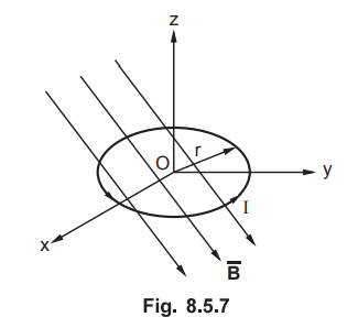
Current
is in ![]() as shown in the Fig. 8.5.7. The given magnetic field is
uniform given by
as shown in the Fig. 8.5.7. The given magnetic field is
uniform given by

The
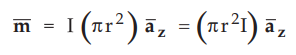
magnetic dipole moment of a planar circular loop is given by,

where
S is the area of the circular loop.
Note
that the loop is laying in z = 0 plane. Thus the direction of unit normal ![]() must be decided by the right hand thumb rule. Let the fingures point in
the direction of current (in
must be decided by the right hand thumb rule. Let the fingures point in
the direction of current (in ![]() direction), then the right thumb gives
the direction of
direction), then the right thumb gives
the direction of ![]() which is clearly
which is clearly ![]() .
.
The
total torque is given by

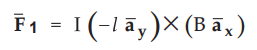
Ex.
8.5.3 A loop wire is bent in the form of triangle as shown in the Fig. 8.5.8. A
current of 100 mA flows in āx direction in the segment AB. If the
uniform magnetic field is ![]() = 0.2āx − 0.1āу +0.2ā2 T find,
= 0.2āx − 0.1āу +0.2ā2 T find,
i)
Force on segment AB ii) Torque on the loop if origin at (0, 0, 0).
Sol.
:
Given
I
= 100 mA = 100 × 10-3 A, ![]() = 0.2āx - 0.1āy
+0.2āz T
= 0.2āx - 0.1āy
+0.2āz T
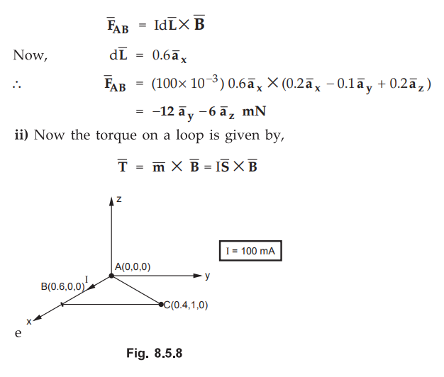
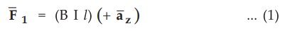
i)
The force exerted on segment AB is given by,
Now area of triangle shaped loop placed in x-y plane can be written in vector form as,

Ex.
8.5.4 What is the maximum torque on a square loop of 1000 turns in a field of
uniform flux density B Tesla ? The loop has 10 cm sides and carries a current
of 3 A. What is the magnetic moment of the loop ?
Sol.
:
The area of a single turn of a square loop of sides 10 cm is given by,
S'
= (l0 × l0-2)(l0 × l0-2) = 0.01m2
Hence
for 1000 turn square loop, the total area is given by,
S
= NS' = (1000) (0.01) = 10 m2 ...
N = Number of turns
The
magnitude of the magnetic dipole moment is given by,
m
= I S = (3) (10) = 30 A• m2
Hence
the magnitude of the maximum torque is given by,
Tmax
= mB = 30 B N • m
Ex.
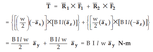
8.5.5 Find the torque about the y-axis for the two conductors of length I,
separated by a distance in the uniform field ![]() as shown in the Fig.
8.5.9.
as shown in the Fig.
8.5.9.

Sol.
:
Both the conductors are of same length I and are separated by a fixed distance
W. The force ![]() , experienced by a conductor to the left of origin is
given by,
, experienced by a conductor to the left of origin is
given by,
Note
that, from the Fig. 8.5.9, ![]() is uniform along + x direction.
is uniform along + x direction.
The
force, ![]() , experienced by a conductor to the right of the origin is
given by,
, experienced by a conductor to the right of the origin is
given by,

The
moment arm of a force ![]() from the left conductor is given by,
from the left conductor is given by,

Similarly
the moment arm of a force ![]() from the right conductor is given by,
from the right conductor is given by,

Thus
the total torque from the left conductor and the right conductor is given by,
Ex.
8.5.6 Find the maximum torque on an 85 turn rectangular coil, 0.2 m by 0.3 m
carrying current of 2 A in a field B = 6.5 T.
Sol.
:
The area of single turn rectangular coil is given by,
S1
= (0.2) (0.3) = 0.06 m2
Hence
for 85 turns of rectangular coil, the total area is given by,
S
= NS1 = (85) (0.06) = 5.1 m2
The
magnitude of the magnetic dipole moment is given by,
m
= IS = (2) (5.1) = 10.2 A.m2
AU
: Dec.-14, Marks 8
Hence
the magnitude of the maximum torque is given by,
Tmax
= mB = (10-2) (6’5) = 663 Nm
Examples
for Practice
Ex.
8.5.7 A small current loop with magnetic
moment 5![]() A-m2 is located at the origin. While another small
current loop L2 with magnetic moment 3
A-m2 is located at the origin. While another small
current loop L2 with magnetic moment 3![]() A-m2 is located at (4,
- 3, 10). Determine the torque on L2.
A-m2 is located at (4,
- 3, 10). Determine the torque on L2.

Ex.
8.5.8 A current of 6 A flows from M(2, 0, 5)
to N(5, 0, 5) in a straight solid conductor in free space. An infinite current
filament lies along z-axis and carries 50 A current in ![]() direction.
Compute vector torque on the wire segment using an origin at (3, 0, 0).
direction.
Compute vector torque on the wire segment using an origin at (3, 0, 0).

Review Questions
1. Derive an expression for torque on a rectangular loop
carrying current I and is situated in uniform magnetic field B Wb/m2
.
2. Define dipole and electromagnetic fields.
3. What is magnetic torque
4. Find an expression for ti loop carrying a currentl.
AU : Dec.-14, Marks 8
5. Find the magnetic field intensity at point P (1.5, 2, 3)
caused by a current filament of 24 ampere in the az direction on the z axis and
extending from z = 0 to z = 6.
AU : May-16, Marks 8
6. Determine the torque on a rectangular loop (a m × b m)
carrying current I and placed in a uniform magnetic field.
AU : May-16, Marks 8
Electromagnetic Theory: Unit III: (b) Magnetic Forces, Magnetic Materials and Inductance : Tag: : with Example Solved Problems - Magnetic Torque and Magnetic Dipole Moment
Related Topics
Related Subjects

Electromagnetic Theory
EE3301 3rd Semester EEE Dept | 2021 Regulation | 3rd Semester EEE Dept 2021 Regulation