Electric Circuit Analysis: Chapter - 1: Basic Circuit Analysis - DC
Mesh current method
Statement, Circuit Diagram, Formula, Solved Example Problems
In mesh method, Kirchhoff's Voltage Law (KVL) is applied to a network. For this network, we have to write mesh equations interms of mesh currents. Here, we are using mesh currents instead of branch currents.
MESH CURRENT METHOD
In
mesh method, Kirchhoff's Voltage Law (KVL) is applied to a network. For this
network, we have to write mesh equations interms of mesh currents. Here, we are
using mesh currents instead of branch currents.
Here,
each mesh is assigned a separate mesh current. Assume that the mesh current
direction is clockwise. Then, KVL is applied to the network, in order to write
equations interms of unknown mesh currents.
The
branch current can be found out by taking the algebraic sum of the mesh
currents which are common to that branch.
The
following steps should be implemented to find out the mesh current and branch currents.
Consider
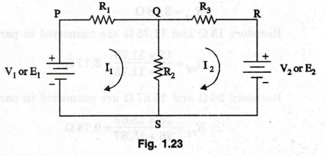
a simple network as shown in figure 1.23.
Step
1:
First, each mesh is assigned a separate mesh currents. Assume all mesh currents
directions are clockwise. Consider the figure 1.23. It consists of two meshes
(PQSP and QRSQ and two mesh currents (I1 and I2).
Step
2:
If two mesh currents (I1 and I2) are flowing through a
network element, the actual current in the circuit element is the algebraic sum
of the two (I1 and I2). In this network, mesh currents, I1
and I2 are flowing through R2. First, we consider one
direction i.e. Q to S, current is I1- I2 and if go for
another direction. i.e., S to Q, current is I1 – I2
Step
3:
Write equation for each mesh in terms of mesh currents by applying KVL. When
writing mesh equations, we assign rise in potential as positive (+) sign and
fall in potential as negative (-) sign.
Step
4:
Suppose any value of mesh current becomes negative in the solution, the actual
or true direction of the mesh current is anticlockwise, i.e., opposite to the
clockwise direction. 00
By
applying KVL to the figure 1.23, we get two equations
Mesh
PQSP
-
I1 R1 – (I1 – I2 ) R2 +
V1 = 0
(or) I1 (R1 + R2 )
– I2 R2 = V1
...(39)
Mesh
QRSQ
-
I2 R3 – V2 (I2 – I1 ) R2
= 0
(or) + I1 R2 – I2
(R2 + R3 ) = V2 ...(39)
The
mesh currents I, and I2 can be found out by solving equations (39) and (40).
Step
5:
The branch currents can be easily found out by using the mesh currents I1
and I2.
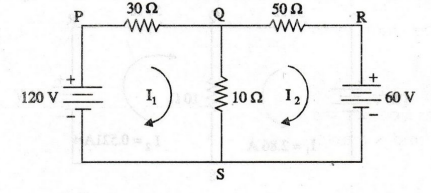
EXAMPLE
85:
Solve the mesh and branch currents shown in figure.
Solution
:
First
assign mesh currents I1 and I2 to meshes PQSP and QRSQ
respectively. It is shown in figure.
Mesh
PQSP
-30
I1 -10 (I1- I2) + 120 = 0
40
I1 -10 I2 = 120
…… (1)
Mesh
QRSQ
-50
I2 – 60 - 10 (I2 – I1) = 0
-10
I1 + 60 I2 = - 60 ……. (2)
The
two equations are
40
I1 -10 I2 = 120
...... (1)
-
10 I1 + 60 I2 = -60 ……. (2)
Multiplying
equation (2) by 4 and adding it to equation (1)
40
I1 -10 I2 = 120
-
40 I1 + 240 I2 =
-240
Solving
these two equations, we can get
I2
= - 0.521 A
The
negative sign indicates that the direction of I2 is anticlockwise. Substituting
I2 value in equation (1) we get,
40
I1 -10 (-0.521) = 120
I1
= 114.79 / 40
I1
= 2.86 A
The
actual direction of flow of mesh currents is shown in figure.
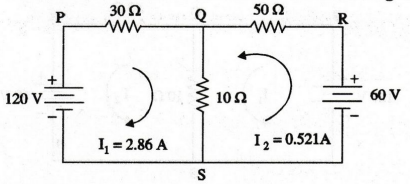
The
mesh current I1 = 2.86 A
I2
= 0.521 A
Current
in branch SPQ, I1 = 2.86 A
Current
in branch SRQ, I2 = 0.521 A
Current
in branch QS= I1 + I2
=
2.86 + 0.521 = 3.381 A
1.97
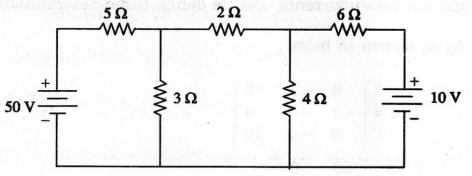
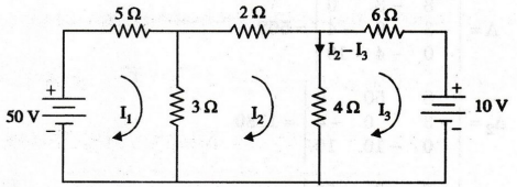
EXAMPLE
86:
Determine the power dissipation in the 4 2 resistor of the circuit show in
figure.
Solution:
First,
we should mark the current direction in the given network. It is shown in the
following figure.
Let
us assume the three mesh currents I1, I2 and I3
as shown in figure. Now, the current flow through 4Ω resistor is I1 –
I3 in the direction shown in figure.
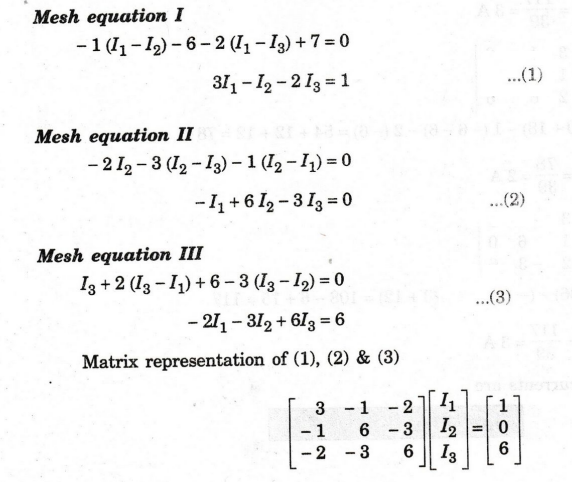
Mesh
equation I
-5
I1-3 (I1 – I2) + 50 = 0
8
I1 - 3 I2 = 50 …. (1)
Mesh
equation II
-2
I2 -4 (I2 – I3) - 3 (I2 – I1)
= 0
-3
I1 + 9 I2 - 4 I3 = 0 ...(2)
Mesh
equation III
-6
I3 – 10 - 4 (I3 - I2) = 0
-
4 I2 + 10 Is = - 10 …… (3)
Matrix
representation of (1), (2) & (3)
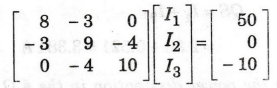
Here,
we have to solve the mesh currents I2 and Ig. By applying Cramer's rule, we can
easily find out mesh currents. Let us define three determinants.
Δ
Δ2 and Δ3 as shown in below.
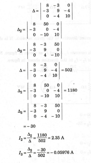
Power
dissipated in the 4 Ω resistor
=
| I2 – I3 |2 × 4
=
[2.35 - (-0.05976)]2 × 4
=
23.22 W
EXAMPLE
87:
Use mesh analysis to determine the three mesh currents in the circuit of
figure shown in below.
Solution
:
The
three required mesh currents are assigned as shown in figure. Applying KVL, we
can get three mesh equations.
Mesh
equation I
Here,
we have to solve the mesh currents 11, 12 and 13, by applying Cramer's rule.
Let us define three determinants,
Δ,
Δ1, Δ2 and Δ3 as shown below.
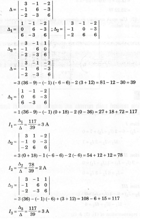
The
three mesh currents are
I1
= 3A; I2 = 2A ; I3 = 3A
EXAMPLE
88:
Determine the value of current through the branch DC of the network shown
below in figure, when the current through the branch BD is zero.
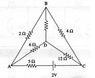
Solution
:
We
have marked in AB as I1 and AD is I2. Since there is no
current in BD, I1 flows through BC and I2 through DC.
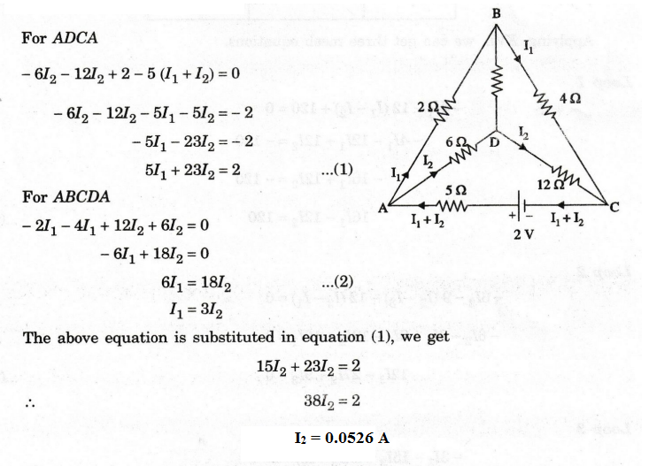
For
ADCA
EXAMPLE
89:
In the circuit given in figure, obtain the load current and power delivered
to the load.
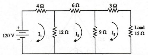
Solution:
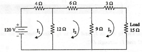
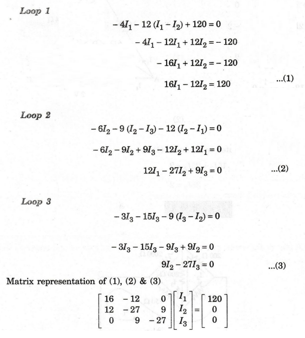
Applying,
KVL, we can get three mesh equations.
By
applying Cramer's rule, we can find out current through load (15Ω). Mesh
current I3 flows through 15 Ω resistor
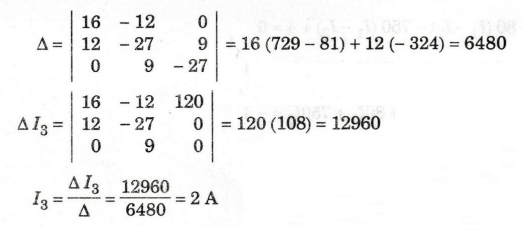
Current
through load resistor (15 Ω) is 2A
Power
delivered to the load = I2R = 22 × 15 = 60 W
EXAMPLE
90:
Determine the current through 800 2 resistor in the network shown in figure.
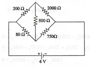
Solution
First
we should mark the current direction in this network. It is shown in figure.
Applying
KVL, we can get three mesh equations.
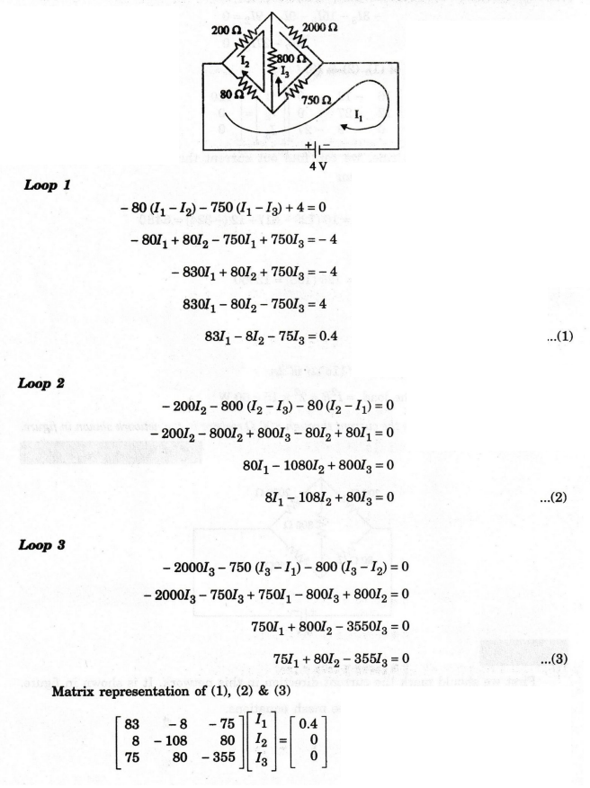
By
applying Cramer's rule, we can find out current through 800 Ω.
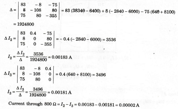
Current
through 800 = I2 – I3 = 0.00183-0.00181 = 0.00002 A
EXAMPLE
91:
In the network of figure, find the current delivered by the battery.
Solution
:
The
three required mesh currents are assigned as shown in figure.
Applying
KVL, we can get three mesh equations.
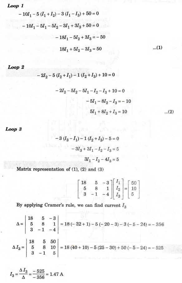
Loop
1
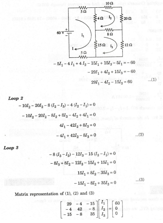
By
applying Cramer's rule, we can find mesh current I1 i.e., current delivered by the
battery.
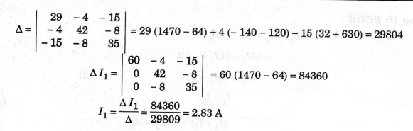
currrent
delivered by the battery = 2.83 A
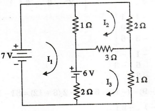
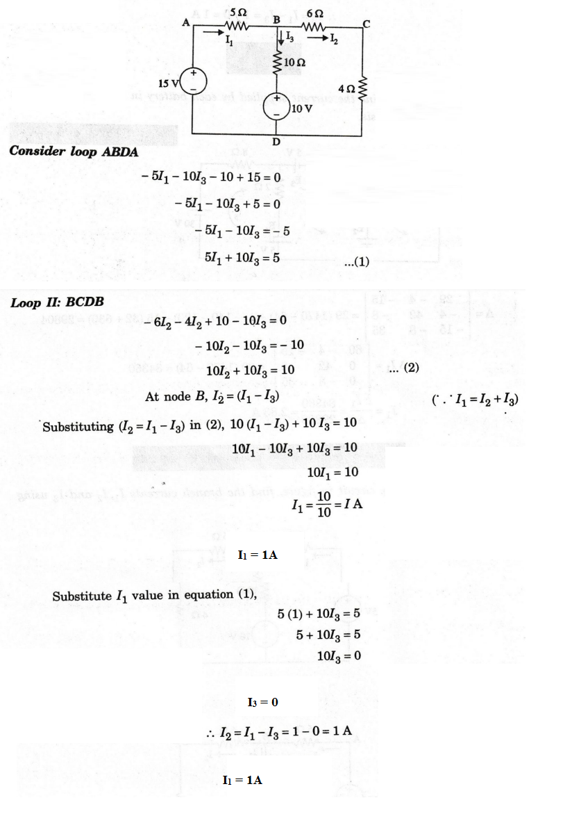
EXAMPLE
92:
For the circuit in figure, find the branch currents I1, 12 and 13 using mesh
analysis.
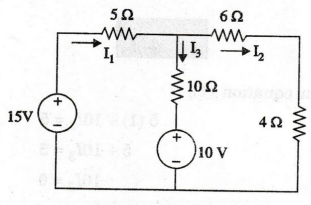
Solution
:
EXAMPLE
93:
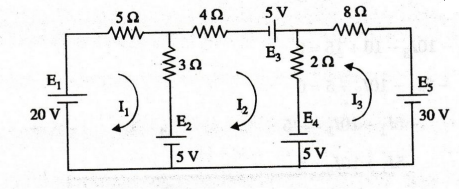
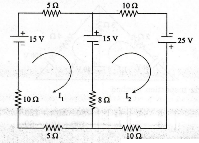
Determine the current supplied by each battery in the circuit shown in
figure using mesh analysis.
Solution
:
The
three loop currents are shown in figure.
Loop
1
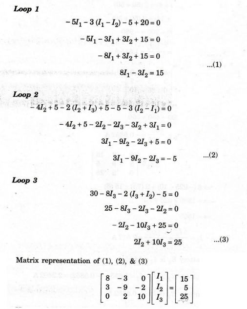
Here
we have to solve the mesh currents I1, I2 and I3
by applying Cramer's rule.
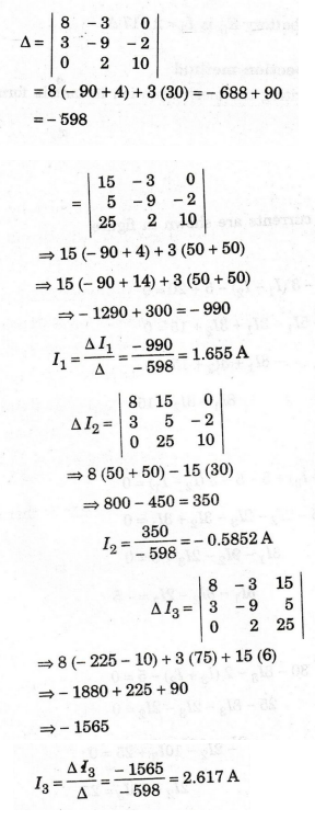
Current
supplied by battery E1 is I1 = 1.655 A
Current
supplied by battery E2 is I1 – I2 = 1.655 –
(-0.5852) = 2.2402A
Current
supplied by battery E3 is I2 = - 0.5852 A
Current
supplied by battery E4 is I3 + I2 = 2.617 – 0.5852 = 2.0318 A
Current
supplied by battery E5 is I3 = 2.617 A
Mesh
equations by inspection method
The
procedure for writing the mesh equation in matrix from can be simplified as
follows.
Steps
1.
Convert the current source into voltage source by source transformation.
2.
All the resistance through which the loop current I1 flows are
summed and denoted by R11. It is called self resistance of loop 1.
3.
All the resistance through which loop currents I1 in the first loop
and I2 in the second loop flow are summed up. This is denoted by R12.
The sign of the term R12 is negative if the two currents I1 and I2
through R12 are in opposite directions; otherwise the sign is positive.
4.
Let V1 be the effective voltage on the first loop through which the
loop current I1 flows. The sign of V1 is positive if the
direction of V1 is same as that of I1 (i.e aiding the
current I1 otherwise the sign of V1 is negative). V1
is written on the right hand side of the equation.
Now,
zero is written on the right hand side if there is no source in the first loop
through which I1 flows.
The
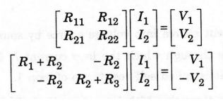
general matrix form of mesh equation is
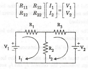
Example
1
Here
the circuit consists of two loops.
R11
= R1+ R2 (Sum of the all resistances in the 1st loop)
R21
= R12 = -R2 (The total resistance shared by the loops one
and two. Negative sign indicates, the current I1 and I2 are
in opposite direction)
R22
= R2 + R3 (Sum of
the all the resistances in the 2nd loop)
First
loop voltage source is V1.
Second
loop voltage source is - V2.
(The minus sign indicates the loop current I2
flows from the voltage terminal + to −)
By
using Cramer's rule, we can find mesh or loop currents I1 and I2.
Example
2
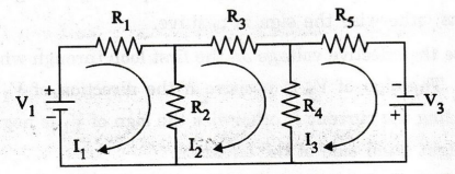
Here,
the circuit consists of three loops. So we have to form 3 × 3 matrix.
R11
= R1+ R2 (Sum of the all the resistances in the 1st
loop)
R12
= R21 = -R2 (The total resistance shared by the loops one
and two. The negative sign, indicate, the current I1 and I2
are in opposite direction)
R13
= R31 = 0 (The total resistance shared by the loops one and three.
Here, no resistance).
R22
= R2 + R3 + R4 (Sum of the all the resistances
in the 2nd loop)
R23
= R32 = -R4 (The total resistance shared by the loops 2
and 3. The negative sign indicate, the current I, and I are in opposite
direction).
R33
= R4 + R5 (Sum of
the all the resistances in the 3rd loop)
Voltage
source in the 1st loop is V1. (Here the V1 is positive
sign. Because, the loop current I1 flows from voltage terminal - to
+).
Voltage
source in the 2nd loop is zero (V2 = 0).
Voltage
source in the 3rd loop is V3
(Here,
the V3 is positive sign. Because the loop current IS
flows from voltage terminal to +).
Now,
the matrix form is
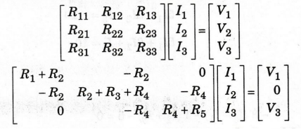
By
using Cramer's rule, we can find mesh currents I1, I2 and
I3.
EXAMPLE
94:
Find the current I3 using mesh analysis.
Solution
:
There
are three loop currents in the above figure.
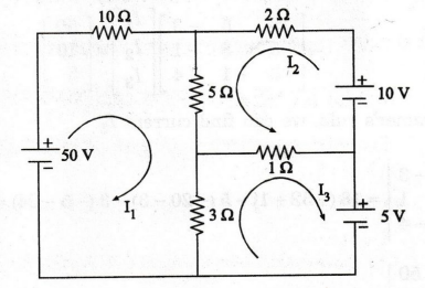
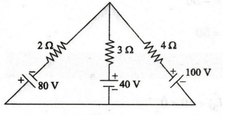
EXAMPLE
95: In the circuit shown in figure, use
mesh analysis to find out the power delivered to the 4 Ω
resistor. To what voltage should the 100 V battery be changed so that no power
is delivered to the 4 Ω resistor?
Solution
:
By
using matrix inspection method
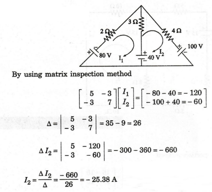
The
negative sign indicates that the direction of I2 is anticlockwise.
I2
= 25.38 A
Power
delivered to the 4 Ω -I22 R = 25.832 × 4
=
2576.57 W
No
power is delivered to the 4 Ω resistor when ΔI2 = 0
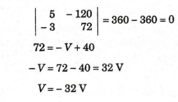
Now
the 100 V battery is changed into 32 V
EXAMPLE
96:
Find the current through the 8 resistor shown in figure.
Solution
:
EXAMPLE
97:
Determine the currents in bridge circuit by using mesh analysis in the
figure. (AU, Trichy/EEE - June 2009)
Solution
:
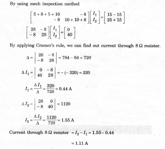
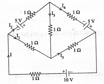
By
using mesh inspection method
By
applying Cramer's rule, we can find out mesh currents i1, i2
and i3.

Current
through branch AD, I1 = i1
– i2 = 7.5 - 6.25 = 1.25 A
Current
through branch AB, I2 = i2 = 6.25 A
Current
through branch BD, I3 = i2 – i3 = 6.25 – 6.25
= 0 A
Current
through branch BC, I4 = i3 = 6.25 A
Current
through branch CD = i1 – i3 = 7.5 - 6.25 = 1.25 A
EXAMPLE
98:
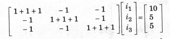
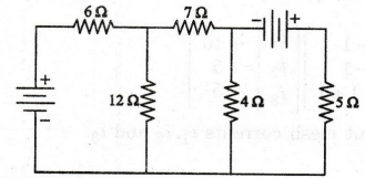
Use mesh method of analysis to find the current through 4 Ω resistor
in the circuit shown in figure. All the DC voltage sources have 12V output.
Solution
:
By
applying mesh inspection method

By
applying Cramer's rule, we find out the current through 4 Ω resistor.
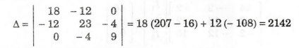
Current through 4 Ω resistor = I3 - I2
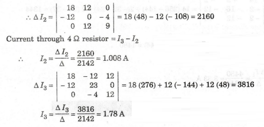
Current
through 4Ω resistor = I3 – I2 = 1.78-1.008 = 0.772 A
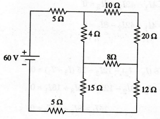
EXAMPLE
99:
For the circuit shown in figure, find the current flowing through the 10 Ω
resistor.
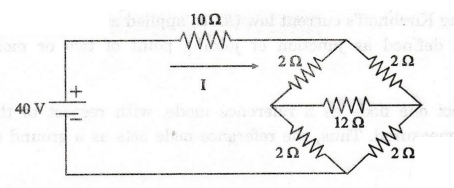
Solution
:
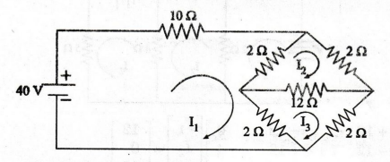
By
applying mesh inspection method
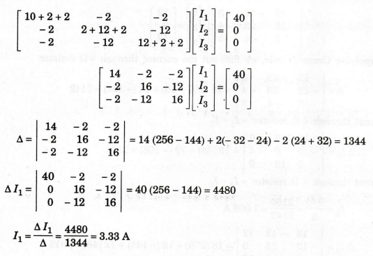
Current
through 10 Ω resistor is 3.33 A
Electric Circuit Analysis: Chapter - 1: Basic Circuit Analysis - DC : Tag: : Statement, Circuit Diagram, Formula, Solved Example Problems - Mesh current method