Basic Civil & Mechanical Engineering: UNIT I: j. Production engineering
Metal cutting
Classification, Principles, Definitions, Tools
A Machine Tool is defined as a power-driven machine which is capable of cutting and removing metal in the form of chips to produce a desired shape.
METAL CUTTING
Machining
Processes: Machining Processes are performed in Metal Cutting
Machines.
Machine
Tools: It is a well-known fact that machine shop forms not
only an important, but an indispensable part of a modern workshop. One should
have a thorough knowledge of the different Metal Cutting Machines, also known
as Machine Tools, their types, principal parts and their functions, and the
various operations that can be performed, etc.
A
Machine Tool is defined as a power-driven machine which is capable of cutting
and removing metal in the form of chips to produce a desired shape.
Chips:
It should be understood that every metal working machine cannot be called a
machine tool for the reason that every machine tools is expected to remove the
metal in the form of chips (Refer Figure). In fact, it would be difficult to
name a product which does not depend in some way upon the machine tools.

Mother
of All Machines: Machine tools are known as the Mother
of All Machines. In a developing country like India where short and long term
programmes have been undertaken in building up heavy industry, machine tools
play a key role in bringing about self-generating economy in the country. Men
in industry today, from company president to apprentice need a good speaking
acquaintance with machine tools. It should, therefore, receive the highest
priority in the field of mechanical engineering.
Classification
of Machine Tools
Machine
tools are classified according to the operations, i.e., type of the surface
generated as follows:
1.
Machine Tools for Cylindrical Work: In this case, the
workpiece is rotated about an axis and tool is traversed in a definite path
relative to the axis, or alternatively, the work may be at rest and the tool is
rotated as well as traversed.
Various
machine tools used for this type of work are Lathe, Turret and Capstan Lathes,
Boring Machine and Cylindrical Grinder.
2.
Machine Tools for Flat Surface Work: For generating a flat
surface, the workpiece is moved past the cutting tool in a straight path and
the tool is traversed in perpendicular direction, or alternatively, the tool is
moved in straight path and work is traversed in perpendicular direction. The
machine tools doing this type of operation are Shaping, Slotting, Planing and
Broaching.
The
flat surface could also be produced by having rotary motion of multi-cutting
edge tool and translatory motion of job. The examples of machine tools
employing such motions are Milling and Surface Grinding Machines.
1. LATHE
Lathe
is the Mother of all Machine Tools. It is a basic machine tool, probably the
most important one of all. Lathe was actually the first machine tool, the
history of which dates back to 18th century. Later developments led to a number
of amendments, as years passed, and the result is what we see today. Further,
lathe formed the basis of production of all other machine tools which are the
results of later developments.
a.
Working Principle
The
main function of a lathe is to remove metal in the form of chips from a
workpiece to give it the required shape and size. This is accomplished by
holding the work securely and rigidly on the lathe and then rotating it against
a cutting tool. The lathe is mainly used to machine cylindrical shapes.
Cutting
Tool: Generally, Single Point Tool is used as the cutting
tool. The tool material should be harder and stronger than the work piece
material.
Lathe
Operations: The main significance of a lathe lies
in the fact that, besides its basic operations of Turning, Facing, Thread
Cutting, etc., it can also perform the operations of other machine tools like
Drilling, Boring, Milling, Gear Cutting, etc. Hence, it is called a Versatile
Machine Tool.
b.
Main Parts of Center Lathe
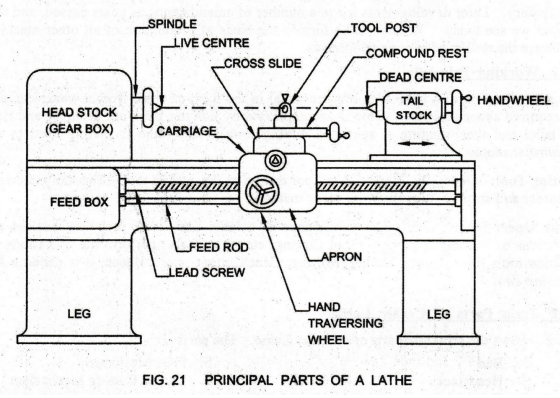
Fig.
21 shows the principal parts of a Center Lathe. The parts are:
1.
Bed
2.
Headstock
3.
Tailstock
4.
Carriage: (a) Saddle, (b) Cross-slide, (c) Compound Rést (d) Tool Post (e)
Apron
5.
Feed Mechanism
6.
Thread Cutting Mechanism
1.
Bed:
It is the base of the lathe. The headstock is mounted on the left end, the
carriage in the middle and the tailstock at the right end of the bed. The bed
has flat or inverted 'V' guideways. The carriage and the tailstock move along
the guideways over the bed.
2.
Headstock: Headstock carries a hollow spindle. A live center
can be fitted into the hollow spindle. The live center rotates with the work
piece and hence called Live Center. The spindle nose is threaded. Chucks or
face plates can be attached to the spindle nose. The headstock has a gear box
(speed changer). Power is transmitted from the headstock to the different parts
of the lathe.
3.
Tailstock: It is mounted on the bed at the right end. It is
used for supporting the right end of the workpiece by means of a dead center.
The dead center does not revolve with the work piece and hence called Dead
Center. However, it can be moved axially by means of a handwheel.
Tailstock
can be moved along the bed for supporting different lengths of workpieces and
clamped at any position. The Tailstock is also used for holding drill and
reamer for drilling and reaming operations.
4.
Carriage: It is supported on the lathe bed-ways. It can move
in a direction parallel to the lathe axis. The carriage is used for giving
various movements to the tool by hand or by power. It carries Saddle,
Cross-slide, Compound Rest, Tool Post and Apron.
a)
Saddle: It carries the Cross Slide, Compound
Rest and Tool Post. It is a H-shaped casting fitted over the bed. It moves
along the guideways.
b)
Cross-slide: It carries the Compound Rest and Tool
Post. It is mounted on the top of the saddle. It can be moved by hand or may be
given power feed through apron mechanism.
c)
Compound Rest: It is mounted on the Cross-slide. It
carries a circular base called Swivel Plate which is graduated in degrees. It
is used during taper turning to set the tool for angular cuts. The upper part
known as Compound Slide can be moved by means of a hand wheel.
d)
Tool Post: It is fitted over the compound rest.
Tool is clamped in the tool post..
e)
Apron: Lower part of the carriage is termed as the Apron.
It is attached to the saddle and hangs in front of the bed. It contains Gears,
Clutches and Levers for moving the carriage by a hand wheel or power feed.
5.
Feed Mechanism
Feed:
The movement of the tool relative to the work piece is termed as Feed. The
lathe tool can be given three types of feed, namely, Longitudinal, Cross and
Angular.
Longitudinal
Feed: When the tool moves parallel to the axis of the
lathe, the movement is called Longitudinal Feed. This is achieved by moving the
carriage.
Cross
Feed: When the tool moves perpendicular to the axis of
the lathe, the movement is called Cross Feed. This is achieved by moving the
cross slide.
Angular
Feed: When the tool moves at an angle to the axis of the
lathe, the movement is called Angular Feed. This is achieved by moving the
compound slide, after swiveling it at an angle to the lathe axis.
Feed
Rod: It is a long shaft, used to move the carriage or
cross-slide for Turning, Facing, Boring and all other operations except Thread
cutting. Power is transmitted from the lathe spindle to the apron gears through
the feed rod via a large number of gears.
6.
Thread Cutting Mechanism: The Lead Screw is a long threaded
shaft used as a master screw. It is brought into operation only when threads
have to be cut. In all other times the lead screw is disengaged from the gear
box and remains stationary. The rotation of the lead screw is used to traverse
the tool along the work to produce screw threads. The half-nut makes the
carriage to engage or disengage the lead screw.
c.
Specifications of a Lathe
The
size of a lathe is specified by
i)
Overall Length of the bed,
ii)
Largest Diameter of the workpiece that can be rotated without touching the guide-ways
of the bed,
iii)
Height of Centers from the bed, and
iv)
Maximum Distance between the Centers.
d.
Operations Performed on Lathe
Operations
performed on a lathe either by holding the workpiece between centers or by a
chuck are: Turning, Facing, Knurling, Forming,
Taper Turning and Thread Cutting.
Operations
performed by holding the workpiece by chuck or face plate are: Grooving,
Parting-Off, Drilling, Reaming, Boring, Counter-Boring and Internal Thread
Cutting..
1.
Turning: (Fig. 22)
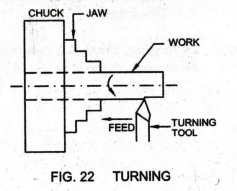
The
workpiece may be held in a chuck as shown or between the centers. The turning
tool is fed parallel to the lathe spindle axis and cylindrical surface is
produced. It reduces the diameter of workpiece.
For
Rough Turning the rate of feed of tool is fast and the depth of cut is heavy.
For this, rough turning tool is used and the depth of cut may be from 2 to 5
mm.
For
Finish Turning feed and depth of cut will be small. For this, a finish turning
tool is used and the depth of cut may be from 0.5 to 1 mm.
2.
Facing: (Fig. 23)

Facing
is the machining of the end face of workpiece to make it flat. The workpiece
may be held in a chuck as shown or between centers. A facing tool is fed
perpendicular to the axis of rotation of workpiece reducing its length.
Only
the face of the workpiece is machined in this process and hence the name
facing.
3.
Drilling: (Fig. 24)
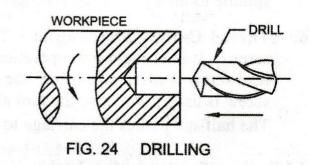
It
is the operation of making a hole in the workpiece. For drilling, the workpiece
is held in a chuck or face plate on one side, whereas the other side remains
free.
Drill:
The
tool used for drilling is called the Drill. From the tail stock, the dead
center is taken out and drill is inserted in it. When the job rotates, the
drill bit is fed into the workpiece by turning the tail stock hand wheel.
Lathe
Tools
Cutting
tools of a lathe have only single cutting edge or point and hence called Single
Point Tools. Most lathe tools are derived from the operation for which they are
designed. For instance, turning tool is meant for turning, facing tool for
facing, etc.
Tool
Materials: Cutting tools used for lathe work are made of :
1.
High-Speed Steel (H.S.S),
2.
High Carbon Steel,
3.
Cemented Carbide and
4.
Diamond.
Note:
In forging, there is a continuous grain flow. In machining, the grain flow is
broken. In casting, there is no grain flow.
Basic Civil & Mechanical Engineering: UNIT I: j. Production engineering : Tag: : Classification, Principles, Definitions, Tools - Metal cutting
Related Topics
Related Subjects

Basic Civil and Mechanical Engineering
BE3255 2nd Semester 2021 Regulation | 2nd Semester EEE Dept 2021 Regulation