Basic Civil & Mechanical Engineering: UNIT I: j. Production engineering
Metal joining processes
Classification, Principles, Applications, Definitions, Advantages, Disadvantages, Limitations
Metal Joining Process is the process of joining of similar or dissimilar metals by the application of heat. It is classified as follows: 1. WELDING 2. SOLDERING 3. BRAZING
METAL JOINING PROCESSES
Metal
Joining Process is the process of joining of similar or dissimilar metals by
the application of heat. It is classified as follows: 1. WELDING 2. SOLDERING
3. BRAZING
1. WELDING
Principles
of Welding
Welding
is the process of joining similar metals by the application of heat. It can be
done with or without the application of pressure and with or without the
addition of filler metal, called Electrodė. The heat may be developed in
several ways for welding operation. The joint obtained is a homogenous mixture
of material of composition and characteristics of the two parent metals.
Nowadays,
many processes of welding have been developed. There is probably no industry
which is not using welding process in the fabrication of its products in some
form or the other. The research carried out in this field has given various
ways and methods to weld practically all metals. Means have also been found out
to weld dissimilar metals.
One
beauty of welding in comparison to other processes of joining metals is that by
this process we can have 100% strength of the joint.
Applications
Welding
is nowadays extensively used in automobile industry, structural work, tanks,
boilers, furniture, pressure vessels, building and bridge constructions,
railway wagons, aircraft machine frames, ship building, pipe-line fabrication
in power plants and refineries, etc. There is a big competition between welding
and casting processes nowadays. Many of the cast products are being fabricated
nowadays by welding various parts together.
Definitions
1.
Parent Metal or Base Metal: The metal to be joined
is known as Parent Metal.
2.
Filler Metal: It is a metal or alloy used to fill the
weld cavity. It has either same composition as the parent metal or added with
alloying element.
3.
Weld Metal: It is the metal that is solidified in
the weld cavity. It may be only metal or a mixture of parent metal and filler
metal.
4.
Edge Preparation: It is the preparation of the edge of
the two metal pieces to be joined..
5.
Weld Pass: It is a single movement of the welding
torch or electrode along the length of the joint.
1.
Gas Welding
Principle:
Gas welding is a type of fusion, non-pressure welding. In this, the required
heat to melt the metal parts is supplied by a high-temperature flame obtained
by a mixture of two gases. The gases are mixed in proper proportions in a
welding blow pipe called Welding Torch. Gas welding is also called as Oxy-Fuel
Gas Welding (OFW), as it uses a fuel gas such as acetylene or hydrogen combined
with oxygen to produce a flame.
The principle of Oxy-Acetylene welding is given below.
See
Fig. 15. An oxy-acetylene weld is produced by heating with a flame obtained
from the combustion of oxygen and acetylene gases.
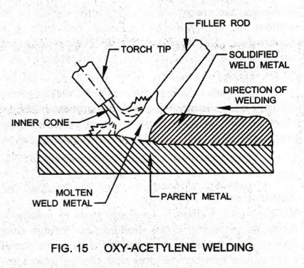
The
temperature of oxy-acetylene flame is 3200°C. The flame will only melt the
metal. Hence, additional metal to the weld is supplied by a Filler Rod.
This
process is suitable for joining metal sheets and plates of thickness varying
from 2 to 50 mm.
In
the case of oxy-hydrogen process, the flame temperature is Steel plates of
thickness up to 7 mm only can be welded.
Filler
Rod or Welding Rod
Filler
Rod or Welding Rod is a metal or alloy rod of diameter 0.3 to 12 mm. It is used
in gas welding for filling the weld cavity to make the joint. It is melted by
the heat of the gas flame and is deposited over the base metals.
Filler
metal is added to the weld for joining metal plates of thickness more than 15
mm.
For
metal plates of thickness less than 15 mm, filler metal is not used.
Filler
rods commonly used are:
-
Low carbon steel rods: Used to weld wrought iron steel plates, steel castings.
-
Mild steel copper coated rods: Used to weld steel plates and pipes.
-
Drawn aluminum rods: Used to weld aluminum sheets, aluminum castings.
Flux
Flux
is used during welding to prevent oxidation and to remove impurities. It is
used except for mild steel which has more silicon and manganese content that
acts as deoxidizing agent.
The
molten metal of the weld comes in contact with gases. Hence, oxidation takes
place and metallic oxides are formed. The flux should have a melting point
lower than the parent metal and filler metal. It readily reacts with metallic
oxides so that the oxides are completely dissolved by the time the molten pool
solidifies. So-formed slag forms a blanket to protect the metal from
atmospheric oxidation.
Advantages
1.
Oxy-acetylene flame is versatile, because it can be used for welding, flame
cutting, brazing and pre-heating.
2.
Temperature of welding can be easily controlled by adjusting the flame. The
flame can be controlled by varying the quantity of oxygen and acetylene by
means of the two control valves provided on the welding torch.
3.
Since the source of heat and the filler rod are separate, the welder has the
required control over filler metal deposition rates. Heat can be supplied
preferentially to the base metal or to the filler rod.
4.
Cost of equipment and also the maintenance cost are reasonably low.
Disadvantages
1.
The process is comparatively slower than arc welding. The gas flame takes up a
longer time to heat up the metal than an electric arc.
2.
It is not suitable for joining thick plates.
3.
Strength of the joint is comparatively less.
4.
Storing and handling of gas cylinders need more care.
2.
Electric Arc Welding
Principle:
The source of heat for Electric Arc Welding is an Electric Arc. The arc is
produced between an electrode and the work or between two metal pieces to be
welded. The electrical energy is converted into heat energy. For arc welding
process, filler metal is required and no mechanical pressure is applied. Hence,
this is one type of fusion welding. Thus, arc welding is defined as the
process of joining two metal parts by melting their edges by an electric arc
using filler rod without the application of pressure.
Arc
Welding Process [Fig. 16]
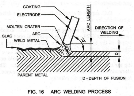
Metal
parts to be welded are cleaned first using wire brush to remove rust, grease,
etc. The electrode is held in the holder. Initially, work and electrode are
touched together and then separated leaving a small air gap of 3 mm
approximately between the electrode tip and the work. This gap is called arc
length.
When
current is passed, an electric arc of about 4000°C temperature is produced
between the electrode tip and the work. Both the electrode and the works are
melted by the arc.
Both
the molten pieces of metal become one. The electrode also deposits additional
filler metal into the joint. The depth to which the metal is melted and deposited
is called Depth of Fusion.
The
electrode is kept inclined at 70° with the work to achieve deep fusion. The
blast of the arc forces the molten metal out of the pool. Hence, a small
depression is formed in the parent metal around which the molten metal is piled
up. This is known as Arc Crater.
The
distance through the center of arc from the tip of electrode to the bottom of
the arc crater is called Arc Length of 3 mm to 4 mm.
The
electrode coating gives off inert gases such as CO2. The inert gases
shield the molten metal pool and prevent it from the atmospheric O2,
H2 and N2. Thus, contamination of weld metal is reduced.
The
coating provides flux to the molten metal pool. Hence, the molten metal mixes
with the oxide and other impurities and forms slag. The slag being lighter
floats at the top. An A.C. transformer or D.C. generator is used for supplying
current. The arc temperature can be increased or decreased by employing high or
low current.
Arc
Welding Equipment
See
Fig. 17. The equipment needed for arc welding process is as follows:
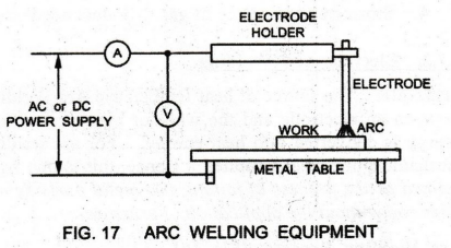
1.
D.C. Generator or A.C. Transformer
2.
Cables – 2 Nos. (one for the workpiece and one for the electrode)
3.
Electrode or filler rod
4.
Electrode Holder
5.
Safety Devices such as goggles, hand gloves, etc.
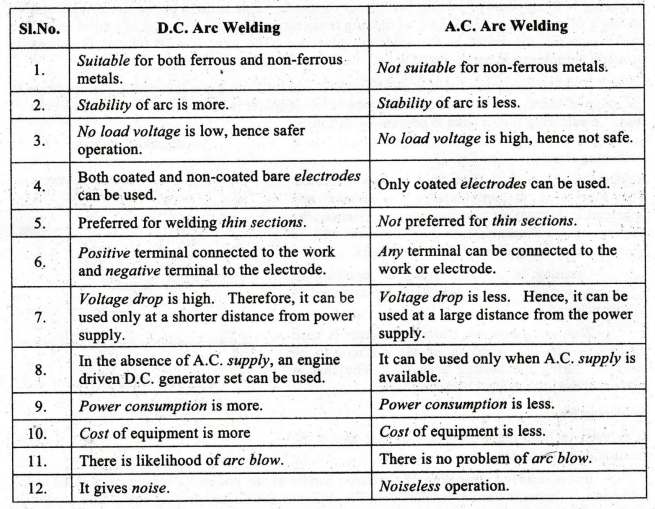
A.C.
or D.C. Machine
Both
direct current and alternating current are used for arc welding, each having
its own merits and demerits.
D
.C. supply is obtained from a generator driven by an electric motor, or if no
electricity is available, by an I.C. engine.
If
electricity supply is available, A.C. transformer is used. It steps down the
usual supply voltage (220 - 440V) to the normal open circuit welding voltage of
40 to 80 Volts. The output of the transformer can be varied by rotating a hand
wheel which alters the air gap and regulates the supply of current.
With
A.C., the heat generated at each pole or end (electrode end and workpiece end)
is the same because of the reversal of the current. Thus, changing over the
connections to the electrode does not have any effect on its performance. In
the case of D.C., the arc heat can be regulated by changing the polarity.
3.
Comparison of D.C. and A.C. Arc Welding
4.
Industrial Applications
-
Arc welding is versatile, producing high quality welds, depositing metal
rapidly.
-
It is competitive cost-wise for many industrial applications such as:
Fabrication of tanks, boilers, pressure vessels, furniture, etc., including in
the structural works of bridges and buildings, automobile industries, aircraft
industries, ship building, etc.
-
It is preferred for difficult tasks like Overhead Welding. Most metals can be
welded by one or more of the forms of arc welding.
2. SOLDERING
Soldering
and Brazing are processes which unite metáls with a third joining metal which
is introduced into the joint in a molten state and allowed to solidify. These
processes have wide commercial use in the uniting of small assemblies and
electrical components.
1.
Soldering Process
Principle
Soldering
is the process of joining two pieces of metal. This is done by the use of heat
and by adding a filler metal, called Solder, of melting temperature 450°C. It
is used as a filler rod. The workpieces are not melted in the soldering
process. The joint is weak due to the adhesion between the solder and parent
metal.
A
solder commonly used is an alloy of tin and lead. It has a low melting
temperature in the range of 150°C - 450°C. A common proportion of solder is
three parts of tin and two parts of lead. A soldering flux is used to prevent
oxidation.
Soldering
Process: See Fig. 18.
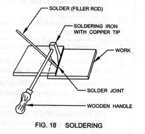
Solder
will not stick to metal that is dirty or rusted. The flux used is not intended
to remove any appreciable amount of contamination. Hence, the surface of the
workpieces is first cleaned well to remove dirt, oil or grease from their
surfaces.
Cleaning
is done by filing or brushing or using emery cloth. The workpieces are arranged
in proper position as shown. Zinc and Ammonia Chloride mixture is used as flux
to prevent oxidation of the surfaces to be soldered during the heating process.
The flux is spread on the joint using a soldering iron.
Soldering
iron:
It
is used to heat the workpieces to just above the melting point of solder.
It
is a steel rod consisting of a wooden handle at one end and a copper tip
pointed at the other end. Copper is used at its end due to its ability to
absorb and give up heat. The copper tip of the soldering iron may be heated
electrically or in gas flame.
Tinning:
In
order to have solder cling to the soldering iron, its tip must be tinned. The
heated tip is dipped in flux and then rubbed on the solder to pick up a thin
film of solder with it. This is called tinning of the tip.
The
solder is melted and the molten solder is picked up by the tip of the soldering
iron and is deposited along the joint. The molten solder joins the two
workpieces and solidifies. A good joint is characterized by a small amount of
solder and perfect adhesion, rather than by large unsightly masses of solder.
Soldering
Fluxes:
The
flux used for soldering is usually in the form of liquid or paste. The flux
fills the space between the soldering iron and the work. Thus, it enables
better heat flow from the iron to the work. The soldering flux may be corrosive
(Zinc Chloride) or non-corrosive (Rosin in alcohol).
2.
Types Of Soldering
1.
Soft Soldering: If the melting point of the filler
metal is very much lower than the melting point of metals to be joined, it is
called soft soldering. The solder is composed of lead and tin with a low
melting point of 150°C – 350°C.
2.
Hard Soldering: The hard solders are alloys of copper
and zinc to which silver is also added. The hard solders melt above 900°C. Hard
soldering produces stronger joints than soft soldering Dip Soldering:
3.
Dip Soldering is based on the method of heating the
joints. It is used for soldering electronic appliances.
3.
Applications of Soldering
The
soldering joints are of low strength. Hence, they should be designed so that
the soldered joint is not relied upon to carry much load. The solder should
serve primarily as a filler material to stop leakage and to seal the joints
against corrosion and also to carry electricity.
Soldering
is hence used for joining wires, repairing radiators, thin sheet metal work,
etc. Soldering provides positive and dependable electrical connections.
The
different compositions of solder for different purposes are:
i)
Soft solder – lead 37 %, tin 63 %
ii)
Plumber's solder – lead 70% , tin 30 %
iii)
Electrician's solder - lead 58%, tin 42%
3. BRAZING
1.
Brazing Process
Principle:
Brazing is the process of joining two similar or dissimilar metals by the use
of heat and a filler metal called Spelter (filler rod). It is similar to
soldering except that spelter is used instead of solder.
Spelter,
a harder filler rod, is having a melting temperature of about 500°C which is
below the melting point of the work metals. Two classes of filler metals used
for most work are copper alloys and silver alloys. Copper alloys made of copper,
zinc and tin are mostly used for brazing ferrous metals. Silver alloys made of
silver and copper with a melting range of 600°C – 800°C are used for brazing
any metals.
Workpieces
are not melted in the brazing process. The flux used for brazing is borax
powder. The molten filler metal (spelter) flows into the joint clearance by
capillary action. The molten filler metal flows between the grain boundaries of
the workpiece metal structure.
Brazing
Process: See Figs. 19(a) and 19(b).
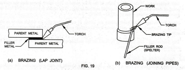
The
metal parts to be brazed should be cleaned first to remove dirt, oil, grease
and rust from their surfaces. Cleaning may be done by brushing, filing or
grinding. Chemical cleaning may also be done using acids. The parts are
assembled and clamped properly in position. The parts are so joined that a gap
should exist between them so that the filler metal may flow inside the joint.
After
cleaning, a small amount of flux (borax powder) is mixed with water to form a
paste. It is evenly applied to the surfaces to be brazed before they are
heated.
Then,
the surfaces to be brazed are heated to a temperature below their melting
point. Heating may be done by oxy-acetylene flame (neutral flame) or in a
furnace. The flux applied on the work surfaces melts and flows in the gap
between the surfaces. When spelter is applied to the joint, it is melted. The
molten spelter flows along the joint, i.e., in the gap between the workpieces
and solidifies, forming a hard brazed joint.
Flux:
The primary function of the flux is to dissolve and absorb oxides which are
formed during heating. It controls the fluidity of brazing metal. The most
common brazing fluxes are borax, fluorides, chlorides and boric acid.
2.
Types of Brazing Based on the Method of Heating
1.
Torch Brazing
Oxy-acetylene
gas flame is widely used for heating the metal parts for brazing. Neutral flame
is applied over the parts by a special torch called brazing torch. Controlling
the flame temperature is difficult. Many types of ferrous and non-ferrous
assemblies and repair works are done.
2.
Dip Brazing
The
parts to be brazed are assembled and dipped into a bath of molten filler metal.
The filler metal flows into the joint. This method is used for joining small
components of metal strips. Suitable holding fixtures are necessary for holding
the parts. Current temperature of the bath can be maintained.
3.
Furnace Brazing
In
this, the parts to be brazed are assembled and kept in a furnace maintained at
a temperature that may melt the filler metal. Brazing temperature can be easily
controlled. Furnace brazing is used for mass production.
3.
Brazing Joints [Fig. 20]
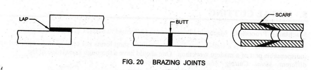
The
basic types of joints done by brazing are lap, butt, and scarf designs are
shown. Lap joint and butt joint are used in sheet metal work. Scarf joint is
used for rod or pipe in any metal.
Advantages
1.
The main advantages of brazing process are the joining of dissimilar metals
(which cannot be welded) and thin sections.
2.
The process is faster.
3.
Brazed joints need not be finished.
4.
Joints are tougher.
Limitations
1.
It has lesser strength compared to welding.
2.
Joint preparation cost is more.
3.
It can be used only for thin sheet metal sections.
4.
Applications
This
process is mostly used for joining pipes (Fig. 19(b)] and other fittings,
carbide tips on steel tool holders, repairing radiators and heat exchangers.
Brass, bronze, copper, steel and stainless steel can be brazed with each other.
Care must be taken when brass or copper parts are brazed, in order that they
shall not be fused. Aluminum is brazed by aluminum alloys that melt just before
the parent metal.
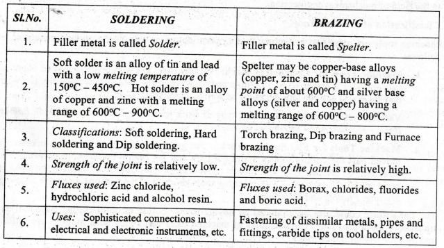
5.
Comparison of Soldering and Brazing
Basic Civil & Mechanical Engineering: UNIT I: j. Production engineering : Tag: : Classification, Principles, Applications, Definitions, Advantages, Disadvantages, Limitations - Metal joining processes
Related Topics
Related Subjects

Basic Civil and Mechanical Engineering
BE3255 2nd Semester 2021 Regulation | 2nd Semester EEE Dept 2021 Regulation