Electrical Machines: Unit II: D.C. Generators
Methods of Improving Commutation
DC Generators
• There are two practical ways by which commutation may be improved. These methods are, 1. Resistance commutation and 2. E.M.F. commutation.
Methods
of Improving Commutation
AU May-03,05,06,
Dec.-09,12,13,17,19
•
There are two practical ways by which commutation may be improved. These
methods are, 1. Resistance commutation and 2. E.M.F. commutation.
1. Resistance Commutation
•
In this method of improving commutation, the low resistance copper brushes are
replaced by high resistance carbon brushes.
•
From the Fig. 3.14.1 it can be seen that the current I from coil C when passing
through commutator segment 'b' has two parallel paths. One is straight from 'b'
to brush while the other is through short circuited coil B to segment 'a' and
then to the brush. By using low resistance copper brush the current will not
prefer second path as it will prefer first low resistance path.

•
When carbon brushes having comparatively high resistance are used then current
I through coil C will select the second path as resistance r1 of
first path will be increasing due to decrease in contact area of 'b' with brush
and resistance r2 of second path will be decreasing due to increase
in contact area of 'a' with brush.
•
Thus by increasing contact resistance between commutator segment and brushes,
will limit short circuit current and reduce time constant (L/P) of the circuit
which will help in quick reversal of current in the desired direction.
a. Advantages of Resistance
Commutation
The
advantages of resistance commutation are,
1.
Upto some degree they are self lubricating and sonpolish the commutator.
2.
If sparking occurs, damage to commutator will be less as compared to when
copper brushes are used.
b. Disadvantages of Resistance
Commutation
The
disadvantages of resistance commutation are,
1.
There is a loss of approximately 2 volts due to high contact resistance. Hence
this is not used in small machines.
2.
If carbon brushes are used the commutator is required to be made somewhat
larger for heat dissipation without rise in temperature which is not necessary
for copper brushes.
3.
Larger brush holders are required due to lower current density (about 7-8 A/cm2).
2. E.M.F. Commutation
•
The method in which reactance voltage produced is neutralized by the reversing e.m.f.
in short circuited coil is called e.m.f. commutation. If the value of this
reversing e.m.f. is made equal to reactance voltage, the effect of reactance
voltage will be completely nullified so that there will be fast reversal of
current which will give sparkless commutation .There are two ways of proving
e.m.f. commutation.
a)
By giving a forward lead to the brushes b) By using interpoles.
a. Giving Brush Shift
•
If the brushes are shifted forward or backward depending on generator or motor,
a little beyond to magnetic neutral axis, the short circuited coil will come
under the influence of main pole of opposite polarity. This will partly
neutralized the reactance voltage which will help in quick current reversal.
This method is rarely used in practice as it will lead to many practical
difficulties.
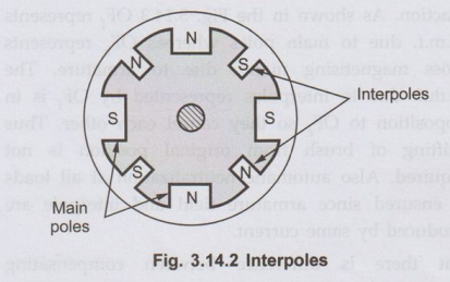
b. Interpoles
•
This method is more suitable and actually used in practice. In this method
reversing e.m.f. required to neutralize reactance voltage is induced in the
coil undergoing commutation by using small poles fixed to the yoke and placed
in between the main poles i.e. along geometrical neutral axis. These poles are
called interpoles. Practically interpoles are placed in between the main poles,
as shown in the Fig. 3.14.2.
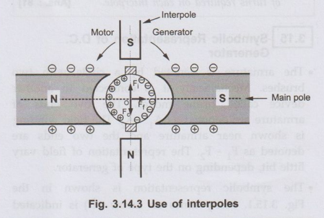
•
On these interpoles few heavy gauge copper wire turns are wound and these are
connected in series with the armature. The polarity of an interpole is same as
the next main pole ahead in the direction of rotation and in case of motor it
is same as main pole behind as shown in the Fig. 3.14.3. The brushes are kept
along the GNA so that coil sides lie directly under the interpoles.
•
The polarity of interpole is same as that of main pole ahead, the induced
e.m.f. in them helps the quick reversal of current. The e.m.f. induced in the
interpoles is called commutating or reversing e.m.f. which will neutralize the
reactance voltage making sparkless commutation.
•
With interpoles sparkless commutation upto 20 to 30 percent overload with fixed
brush position can be obtained. Hence sparking limit is at same value as that
of heating limit. So for given output the machine can be made smaller and will
be cheaper than non-interpolar machine.
•
Also by using interpoles automatic neutralization of reactance voltage at all
loads is ensured since it is connected in series with armature and reactance
and reversing e.m.f.s are proportional to armature current.
•
Although interpoles mainly provide reversing e.m.f. opposite to that of
reactance voltage, the other advantage of using interpoles is that they help in
neutralizing cross magnetising effect of armature reaction. As shown in the
Fig. 3.14.3 OFf, represents m.m.f. due to main poles whereas OFf
represents cross magnetising m.m.f. due to armature. The m.m.f. due to
interpoles represented by OFi, is in opposition to OF, so they
cancel each other. Thus shifting of brush from original position is not
required. Also automatic neutralization at all loads is ensured since armature
field and interpole are produced by same current.
•
But there is difference between compensating winding and interpoles. The two
are connected in series and both will try to neutralize armature reaction
effect. But interpoles in addition supply reversing e.m.f. to improve
commutation. In addition to this, the action of interpoles is localized near
the commutating area only. It has negligible effect on armature reaction
occurring on the remaining part of the armature periphery.
Key Point:
So armature reaction effect can be completely neutralized by using interpoles
as well as compensating winding.
Review Questions
1. Explain the
methods adopted to improve commutation.
AU: May-03,
Dec.-09,12,13,17,19, Marks 8
2. Explain the
functions of interpoles in a d.c. machine.
3. A 440 V, 4 pole,
25 kW d.c. generator has a wave connected armature winding with 846 conductors.
The mean flux density in the air gap under the interpoles is 0.5 Wb/m2
on full load and the radial gap length is 0.4 cm. Calculate the number of turns
required on each interpole. [Ans.: 81]
Electrical Machines: Unit II: D.C. Generators : Tag: : DC Generators - Methods of Improving Commutation
Related Topics
Related Subjects

Electrical Machines I
EE3303 EM 1 3rd Semester EEE Dept | 2021 Regulation | 3rd Semester EEE Dept 2021 Regulation