Electric Circuit Analysis: Chapter - 2: Network Theorems - DC
Millman's Theorem
Statement, Proof, Circuit Diagram, Formula, Solved Example Problems
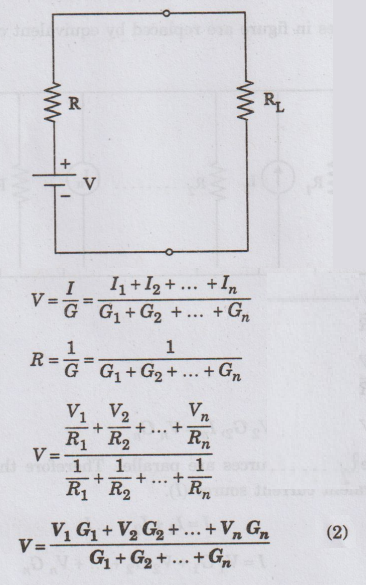
Millman's Theorem states that 'n' voltage sources (V1, V2, ... Vn) are in parallel having their internal resistances (R1, R2, ... Rn) respectively. The arrangement can be replaced by a single voltage source 'V' and resistance 'R' as given below figure (a) (b).
MILLMAN'S THEOREM
Statement
Millman's
Theorem states that 'n' voltage sources (V1, V2, ... Vn)
are in parallel having their internal resistances (R1, R2,
... Rn) respectively. The arrangement can be replaced by a single
voltage source 'V' and resistance 'R' as given below figure (a) (b).
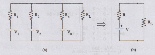
(a)
A number of parallel voltage sources feeding power to a load resistance.
(b)
Equivalent voltage (V) and resistance (R) of the source network following
Millman's Theorem.
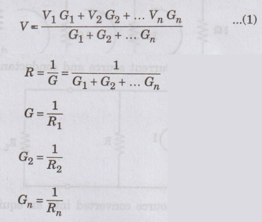
As
per Millman's Theorem,
Proof
The
voltage sources in figure are replaced by equivalent current sources as shown
in figure.
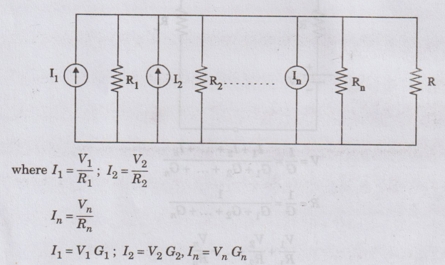
Here
all the current sources are parallel. Therefore this circuit may be replaced by
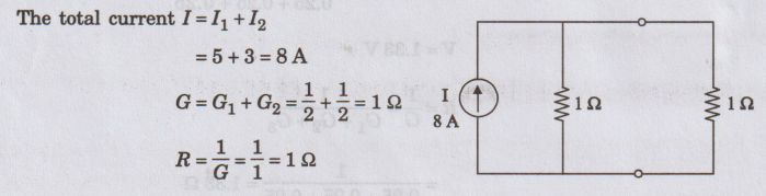
a single equivalent current source (I).
I
= I1 + I2 + ... In
I
= V1 G1 + V2 G2 + ... + Vn
Gn
All
the conductances are in parallel in this circuit diagram of figure can be
replaced by a single equivalent conductance (G).
G
= G1 + G2 +...+ Gn
R
= 1/ G
Figure
shows equivalent current source and conductance
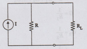
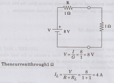
This
equivalent current source converted into an equivalent voltage source. It is
shown in figure.
Here
Millman's theorem is proved.
EXAMPLE
40: Using millman's theorem find the current through RL
in the circuit shown in figure and find the voltage across R.
Solution:
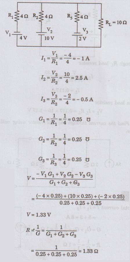
The
equivalent circuit of Millman's theorem is
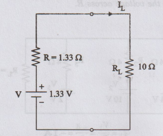
Current
through RL load resistor
IL
= V / R + RL = 1.33 / 1.33 + 10
IL
= 0.117 A
Voltage
cross load resistor
VL
= IL RL = 0.117 × 10 = 1.17 V
EXAMPLE
41:
Find the current through the 12 resistor using millman's theorem of figure
given below.
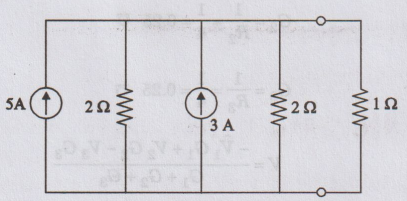
Solution
:
Now
this circuit converted into equivalent voltage source.
Electric Circuit Analysis: Chapter - 2: Network Theorems - DC : Tag: : Statement, Proof, Circuit Diagram, Formula, Solved Example Problems - Millman's Theorem