Microprocessors and Microcontrollers: Unit IV: (c) Programmable Interval Timer (PIT/C) 8253/8254
Mode Definition
Programmable Interval Timer (PIT/C) 8253/8254
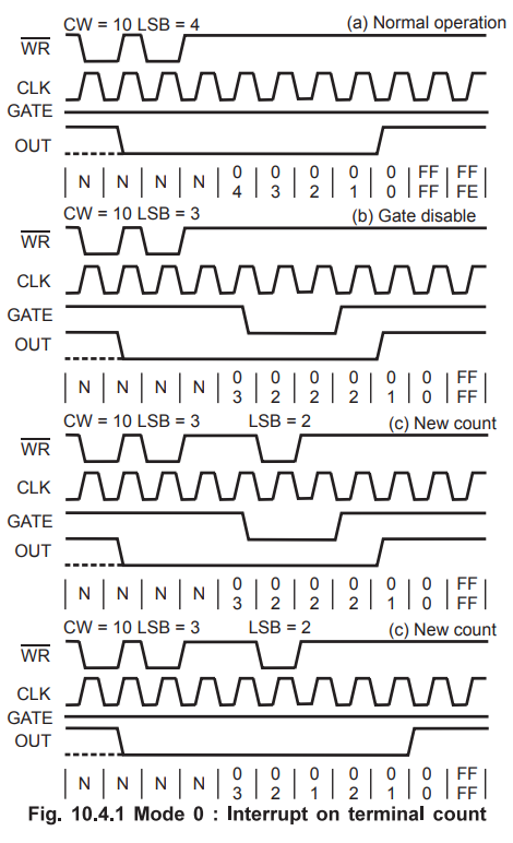
Mode 0 : Interrupt on terminal count
Mode Definition
Mode
0 : Interrupt on terminal count
a)
Normal Operation : 1) The output will be initially low
after the mode set operation. 2) After the count is loaded into the selected
count Register the output will remain low and the counter will count. 3) When
the terminal count is reached the output will go high and remain high until the
selected count is reloaded.
b)
Gate Disable :
1)
Gate = 1 enables counting.
2)
Gate = 0 disables counting.
Note
:
Gate has no effect on OUT.
c)
New Count : If a new count is written to the
counter, it will be loaded on the next CLK pulse and counting will continue
from the new count.
In
case of two byte count :
1)
Writing the first byte disables counting.
2)
Writing the second byte loads the new count on the next CLK pulse and counting
will continue from the new count.
MODE
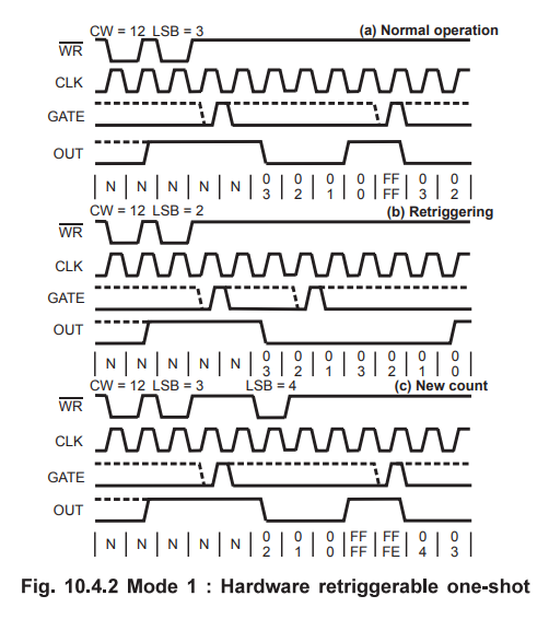
1 : Hardware Retriggerable One
a)
Normal operation :
1)
The output will be initially high.
2)
The output will go low on the CLK pulse following the rising edge at the gate
input.
3)
The output will go high on the terminal count and remain high until the next
rising edge at the gate input.
b)
Retriggering: The one shot is retriggerable, hence
the output will remain low for the full count after any rising edge of the gate
input.
c)
New count:
If
the counter is loaded during one shot pulse, the current one shot is not
affected unless the counter is retriggered. If retriggered, the counter is
loaded with the new count and the one-shot pulse continues until the new count
expires.
MODE
2: Rate generator
This
mode functions like a divide by-N counter.
a)
Normal operation :
1)
The output will be initially high.
2)
The output will go low for one clock pulse before the terminal count.
3) The output then goes high, the counter reloads the initial count and the process is repeated.
4)
The period from one output pulse to the next equals the number of input counts
in the count register.
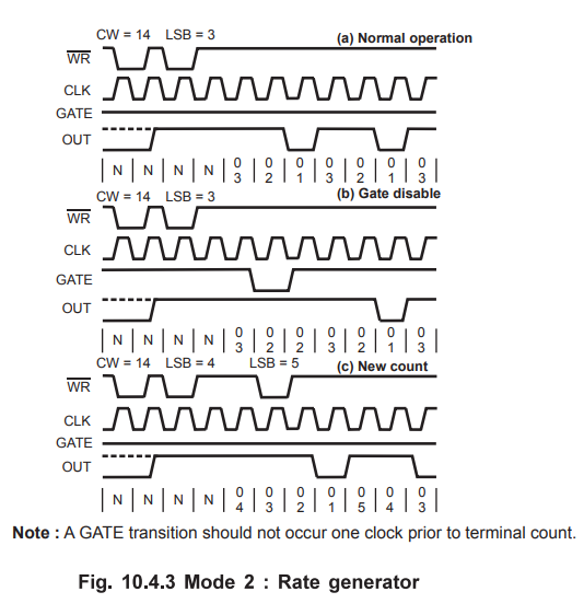
b)
Gate disable :
1)
If Gate = 1 it enables a counting otherwise it disables counting (Gate = 0 ).
2)
If Gate goes low during an low output pulse, output is set immediately high. A
trigger reloads the count and the normal sequence is repeated.
c)
New count : The current counting sequence does not
affect when the new count is written. If a trigger is received after writing a
new count but before the end of the current period, the new count will be
loaded with the new count on the next CLK pulse and counting will continue from
the new count. Otherwise, the new count will be loaded at the end of the
current counting cycle.
Note
In mode 2, a count of 1 is illegal.
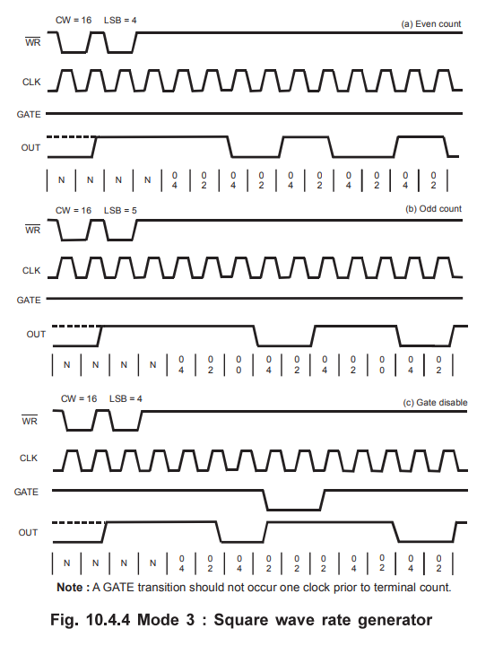
MODE 3 : Square Wave Rate Generator
a)
Normal operation :
1)
Initially output is high.
2)
For even count, counter is decremented by 2 on the falling edge of each clock
pulse. When the counter reaches terminal count, the state of the output is
changed and the counter is reloaded with the full count and the whole process
is repeated.
3)
If the count is odd and the output is high the first clock pulse (after the count
is loaded) decrements the count by 1. Subsequent clock pulses decrement the
clock by 2. After timeout, the output goes low and the full count is reloaded.
The first clock pulse (following the reload) decrements the
b)
Gate disable : If Gate is 1 counting is enabled
otherwise it is disabled. If Gate goes low while output is low, output is set
high immediately. After this, When Gate goes high, the counter is loaded with
the initial count on the next clock pulse and the sequence is repeated.
c)
New count : The current counting sequence does not
affect when the new count is written. If a trigger is received after writing a
new count but before the end of the current half-cycle of the square wave, the
counter will be loaded with the new count on the next CLK pulse and counting
will continue from the new count. Otherwise, the new count will be loaded at
end of the current half-cycle.
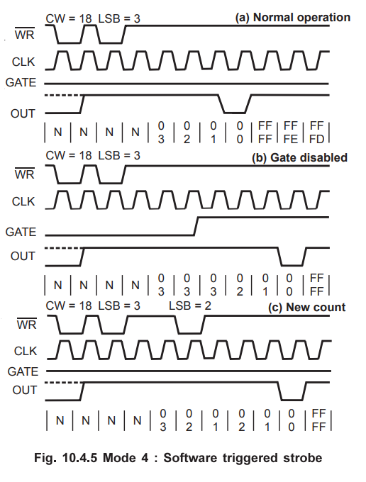
MODE
4 : Software Triggered Strobe
a)
Normal operation:
1)
The output will be initially high.
2)
The output will go low for one CLK pulse after the terminal count (TC).
b)
Gate Disable: If Gate is one the counting is enabled
otherwise it is disabled. The Gate has no effect on the output.
c)
New count: If a new count is written during counting, it will
be loaded on the next CLK pulse and counting will continue from the new count.
If the count is two byte then
1)
Writing the first byte has no effect on counting.
2)
Writing the second byte allows the new count to be loaded on the next CLK pulse.
MODE
5 : Hardware triggered strobe (Retriggerable).
a)
Normal operation :
1)
The output will be initially high.
2)
The counting is triggered by the rising edge of the Gate.
3)
The output will go low for one CLK pulse after the terminal count (TC).
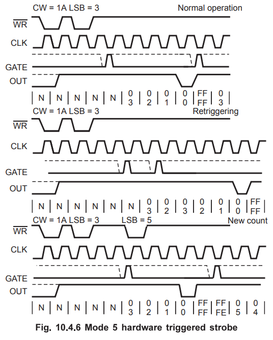
b)
Retriggering : If the triggering occurs on the Gate
input during the counting, the initial count is loaded on the next CLK pulse
and the counting will be continued until the terminal count is reached.
c)
New count : If a new count is written during
counting, the current counting sequence will not be affected. If the trigger
occurs after the new count is written but before the terminal count, the
counter will be loaded with the new count on the next CLK pulse and counting
will continue from there.
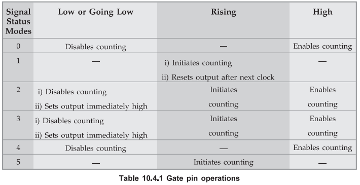
Table
10.4.1 shows the gate pin operations.
Review
Questions
1.
Discuss various operating modes of 8253 timer with necessary control words. AU
: June-07, Dec.-ll, Marks 16
2.
Explain the different operating modes of 8253 timer.
AU : Dec-12, 17, Marks 8
3. Explain modes of the 8254 timer. AU : Dec,-15, Marks 4
Microprocessors and Microcontrollers: Unit IV: (c) Programmable Interval Timer (PIT/C) 8253/8254 : Tag: : Programmable Interval Timer (PIT/C) 8253/8254 - Mode Definition