Linear Integrated Circuits: Unit III: Applications of Op-amp
Monostable Multivibrator using Op-amp
Working Principle, Pulse, Circuit Diagram
There are three types of multivibrator circuits in use, namely, a) Bistable multivibrator b) Monostable multivibrator c) Astable multivibrator Let us see the basic concept behind the operation of these three types of multivibrators.
Monostable Multivibrator using Op-amp
The
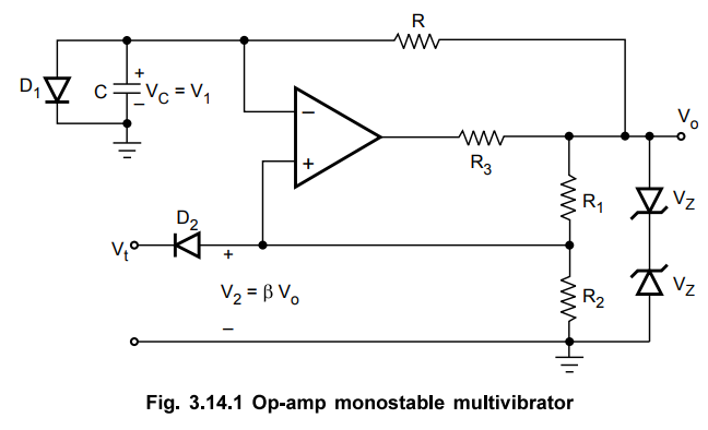
monostable multivibrator circuit using op-amp is shown in the Fig. 3.14.1.
The
diode D1 is clamping diode connected across C. The diode clamps the
capacitor voltage to 0.7 V when the output is at +Vsat. A narrow
negative triggering pulse Vt is applied to the noninverting input
terminal, through diode D2.
Let
us see the operation of the circuit.
To
understand the operation of the circuit, let us assume that the output Vo is at
+Vsat i.e. in its stable state. The diode D1 conducts and
the voltage across the capacitor C i.e. VC gets clamped to 0.7 V.
The voltage at the non-inverting input terminal is controlled by potentiometric
divider of R1R2 to β Vo i.e. + 3 Vsat
in the stable state.
Now
if Vt, a negative trigger of amplitude Vt is applied to
the non-inverting terminal, so that the effective voltage at this terminal is
less than 0.7 V (+ β Vsat + (- Vt)) then the output of
the op-amp changes its state from + Vsat to - Vsat.
The
diode is now reverse biased and the capacitor starts charging exponentially to
- Vsat through the resistance R. The time constant of this charging is τ = RC.
The
voltage at the non-inverting input terminal is now - β Vsat. When
the capacitor voltage VC becomes just slightly more negative than - β
Vsat, the output of the op-amp changes its state back to + Vsat.
The
capacitor now starts charging towards + Vsat through R until VC
reaches 0.7 V as capacitor gets clamped to the voltage.
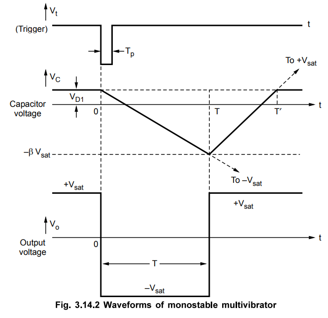
The
waveforms are shown in the Fig. 3.14.2.
1. Expression for Pulse Width T
For
a low pass RC circuit let,
Vi
= Initial value of the voltage
Vf
= Final value of the voltage
Then
the general solution is given by,
Vo
= Vf + (Vi - Vf) e-t/RC ...(3.14.1)\
Now
for the monostable multivibrator discussed above, the values of Vf and Vi are,
Vf
= - Vsat and Vi = VD1 (diode forward voltage)
while Vo = Output = Capacitor voltage = VC
VC
-Vsat + (VD1-[-Vsat])e-t/RC …. (3.14.2)
at t = T, VC = -β Vsat …. (3.14.3)
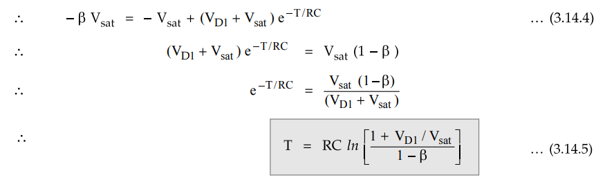
This
is obtained by absorbing negative sign inside the natural logarithm. The
potential divider decides the value of 3 given by,
β
= R2 / R1 + R2
… (3.14.6)
If
Vsat >> VD1 and R1 = R2 so
that β = 0.5, then
T
= 0.69 RC …. (3.14.7)
For
monostable operation, the trigger pulse width Tp should be much less
than T, the pulse width of the monostable multivibrator.
The
diode D2 is not essential but it is used to avoid malfunctioning if
any positive noise spikes are present in the triggering line. It can be seen
from the waveform that the voltage VC does not reach its quiescent
value VD1 until time T' > T. Hence it is necessary that a
recovery time T' - T be allowed to elapse before the next triggering signal is
applied.
Review Question
1. Draw the circuit of monostable multivibrator and obtain
expression for pulse width.
Dec.-07, 09, Marks 8
Linear Integrated Circuits: Unit III: Applications of Op-amp : Tag: : Working Principle, Pulse, Circuit Diagram - Monostable Multivibrator using Op-amp
Related Topics
Related Subjects

Linear Integrated Circuits
EE3402 Lic Operational Amplifiers 4th Semester EEE Dept | 2021 Regulation | 4th Semester EEE Dept 2021 Regulation