Electric Circuit Analysis: Unit V: Resonance and coupled circuits
Mutual inductance
Definition, Formula, Derivation
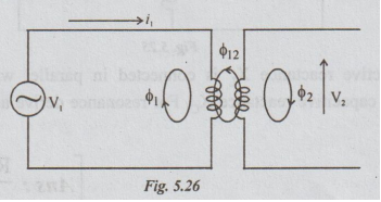
Consider the circuit shown in fig. 5.26, the changing current i, produces a variable flux 1 in the first coil. For the purpose of analysis, ϕ1 is divided into two components.
MUTUAL INDUCTANCE
Consider
the circuit shown in fig. 5.26, the changing current i, produces a variable
flux 1 in the first coil. For the purpose of analysis, ϕ1 is divided
into two components.
ϕ1
= ϕ11 + ϕ12 ... (6)
Here
ϕ1 is the total flux established by i1, ϕ11 =
a part of ϕ1. It links with coil 1 only but not with coil 2.
ϕ12
= it is a part of 1. It links with both coils 2 and 1.
As,
the flux linking with coil 2 changes, an e.m.f. is induced in the coil ϕ2 and
is given by
e2
= N2 dϕ12 / dt … (7)
Also, e2 is proportional to time rate of change of i. It is because ϕ12 is produced by i,, therefore,
e2
= M di1/dt ... (8)
From
equations (7) and (8), we can write that,
M
= N2 dϕ12 / di1 ... (9)
If
the permeability is constant, the above equation becomes
M
= N2 dϕ12 / i1 ... (10)
Suppose
that the second coil is connected to a voltage source. Let i2 be the
current flow and ϕ2 be the total flux.
ϕ2
= ϕ22 + ϕ21
Here,
ϕ21 is a part of ϕ2 and links with coil 1. Then, the
e.m.f. in the coil 1 = e1.
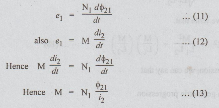
In
equations (10 & 13) M is called mutual inductance.
Definition
of M
The
mutual inductance between 2 coils is defined as the weber turns in one coil per
ampere current in other coil. It is measured in henrys.
The
mutual inductance is also defined as the ability of one coil to produce e.m.f.
in other coil by induction when the current in the first changes.
Coefficient
of coupling (K) or coefficient of magnetic coupling (KM).
Consider
the fig. 5.19, the fraction of the total flux produced by coil 1 linking coil 2
is ϕ12 / ϕ1 . It is called coefficient of coupling. Thus
K
= ϕ12 / ϕ1 … (14)
Also
K = ϕ21 / ϕ2 ...
(15)
Multiplying
equations (10) & (13), we get
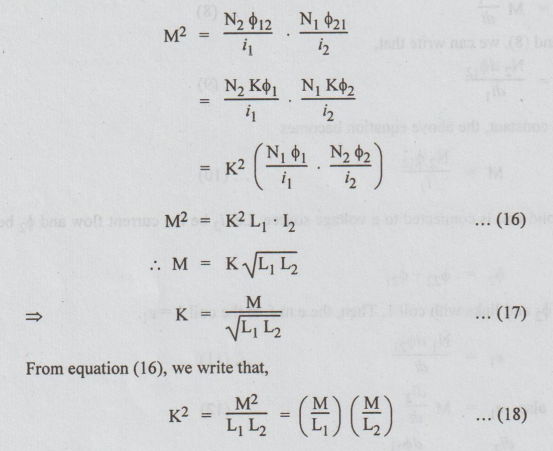
From
the above expression, we can say that
M
/ L1, and M / L2 are in geometric progression.
Note:
(i) The values of K depends on spacing,
orientation of the coils and on the permeability of the medium.
(ii)
It is a non-negative number and is independent of the reference directions of
the currents. d lio
(iii)
If the coils are at great distance apart, M is very small and hence K.
(iv)
For iron-core coupled circuits, K may be as high as 0.99.
(v)
For air-core coupled circuits, K varies between 0.4 and 0.8.
(vi) The maximum value of K is 1. Hence Mmax = √L1 L2.
Electric Circuit Analysis: Unit V: Resonance and coupled circuits : Tag: : Definition, Formula, Derivation - Mutual inductance
Related Topics
Related Subjects

Electric Circuit Analysis
EE3251 2nd Semester 2021 Regulation | 2nd Semester EEE Dept 2021 Regulation