Electrical Machines: Unit I: a. Magnetic Circuits and Electromagnetism
Nature of the Induced E.M.F.
Dynamically, Statically
Depending upon the nature of methods, the induced e.m.f. is classified as, 1) Dynamically induced e.m.f. and 2) Statically induced e.m.f
Nature of
the Induced E.M.F.
AU : May-12, Dec.-13,14,15,16,19
•
E.M.F. gets induced in a conductor, whenever there exists change in flux with
that conductor, according to Faraday's Law. Such change in flux can be brought
about by different methods.
•
Depending upon the nature of methods, the induced e.m.f. is classified as,
1)
Dynamically induced e.m.f. and
2) Statically induced e.m.f
1. Dynamically Induced E.M.F.
•
The change in the flux linking with a coil, conductor or circuit can be brought
about by its motion relative to magnetic field. This is possible by moving flux
with respect to coil conductor or circuit or it is possible by moving
conductor, coil, circuit with respect to stationary magnetic flux. Both these
methods are discussed earlier in discussion of Faraday's experiment
Key Point :
Such an induced e.m.f. which is due to physical movement of coil, conductor
with respect to flux or movement of magnet with respect to stationary coil,
conductor is called dynamically induced e.m.f. or motional induced e.m.f.
a. Magnitude of Dynamically Induced
E.M.F.
• Consider a conductor of length 1 metres
moving in the air gap between the poles of the magnet.
If
plane of the motion of the conductor is parallel to the plane of the magnetic
field then there is no cutting of flux lines and there can not be any induced
e.m.f. in the conductor such condition is shown in the Fig. 1.22.1 (a).
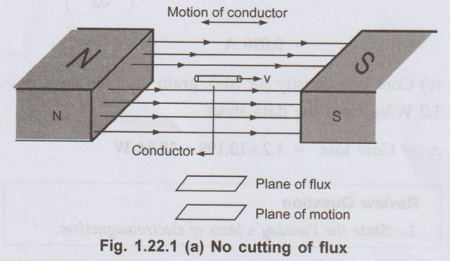
Key Point :
When plane of the flux is parallel to the plane of the motion of conductors
then there is no cutting of flux, hence no induced e.m.f.
•In
second case as shown in the Fig. 1.22.1 (b), the velocity direction i.e. motion
of conductor is perpendicular to the flux. Hence whole length of conductor is
cutting the flux line hence there is maximum possible induced e.m.f. in the
conductor. Under such condition plane of flux and plane of motion are
perpendicular to each other.
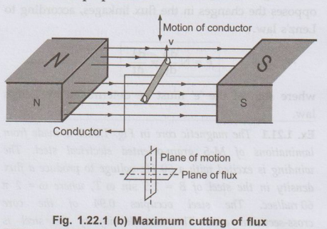
Key Point :
When plane of the flux is perpendicular to the plane of the motion of the
conductors then the cutting of flux is maximum and hence induced e.m.f. is also
maximum.
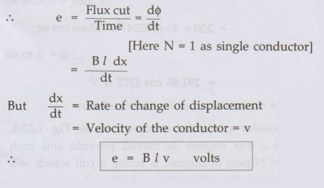
Consider a conductor moving with velocity v m/s such that its plane of motion or direction of velocity is perpendicular to the direction of flux lines as shown in Fig. 1.22.2 (a).
B = Flux density in Wb/m2
l = Active length of conductor in
metres.
(This
is the length of conductor which is actually responsible for cutting of flux
lines.)
V
= Velocity in m/sec.
Let
this conductor is moved through distance dx in a small time interval dt, then
Area
swept by conductor = 1 × dx m2
ஃ Flux cut by conductor = Flux density × Area swept
dϕ = B×l× dx Wb
According to Faraday's law, magnitude of
induced e.m.f. is proportional to the rate of change of flux.
•
This is the induced e.m.f. when plane of motion is exactly perpendicular to the
plane of flux. This is maximum possible e.m.f. as plane of motion is at right
angles to plane of the flux.
• But if conductor is moving with a velocity v but at a certain angle O measured with respect to direction of the field (plane of the flux) as shown in the Fig. 1.22.2 (b) then component of velocity which is v sin 0 is perpendicular to the direction of flux and hence responsible for the induced e.m.f. The other component v cos O is parallel to the plane of the flux and hence will not contribute to the dynamically induced e.m.f.
•
Under this condition magnitude of induced e.m.f. is given by,
e
= B l v sin θ volts
where
θ is measured with respect to plane of
the flux.
Ex. 1.22.1
A conductor of 2 m length moves with a uniform velocity of 1.27 m/sec under
a magnetic field having a flux density of 1.2 Wb/m2 (tesla).
Calculate the magnitude of induced e.m.f. if conductor moves,
i)At
right angles to axis of field.
ii)
At an angle of 60° to the direction of field.
Sol. : The magnitude of induced e.m.f.

Ex.
1.22.2 A coil carries 200 turns gives rise a flux of 500
μWb when carrying a certain current. If this current is reversed in 1/10 th of
a second. Find the average e.m.f. induced in the coil.
Sol.
The magnitude of induced e.m.f. is,
=
N d ϕ
/ dt
where
d ϕ
is change in flux linkages i.e. change in N ϕ. Now in this problem
flux is 500 × 10-6 for given current. After reversing this current,
flux will reverse its direction. So flux becomes (-500 × 10-6).
.
d ϕ = ϕ2 – ϕ1 -500× 10-6 -(+ 500 × 10-6)
This
happens in time dt = 0.1 sec.
Average
e.m.f. = N d ϕ / dt = -200× (-1 × 10³ / 0.1)
=
2 volts
Ex. 1.22.3 An electric conductor of effective length of 0.3 metre is made to move with a constant velocity of 5 metre per second perpendicular to a magnetic field of uniform flux density 0.5 tesla. Find the e.m.f. induced in it. If this e.m.f. is used to supply a current of 25 A, find the force on the conductor, and state its direction w.r.t. motion of conductor, ignoring friction. Find the power required to keep the conductor moving across the field.
Sol :
1 = 0.3 m, v = 5 m/s, B = 0.5 T
ஃ e = Blv = 0.3 × 5 × 0.5 = 0.75 V and I = 25 A
ஃ F = BI l = 0.5 × 25 × 0.3 = 3.75 N
The direction of this force is so as to
oppose the motion of conductor, as per Lenz's law. The power required to keep
the conductor moving is,
P
= e × I = 0.75 × 3.75 = 2.8125 W
b. Direction of Dynamically Induced
E.M.F.
The direction of induced e.m.f. can be decided
by using two rules.
1) Fleming's Right Hand Rule :
Fleming's Right Hand Rule is to used to get
direction of induced e.m.f. when conductor is moving in a magnetic field.
According to Fleming's right hand rule, outstretch the three fingers of right hand namely the thumb, fore finger and the middle finger, perpendicular to each other. Arrange the right hand so that first finger point in the direction of flux lines (from N to S) and thumb in the direction of motion of conductor with respect to the flux then the middle finger will point in the direction of the induced e.m.f. (or current). The rule is shown in the Fig. 1.22.3.

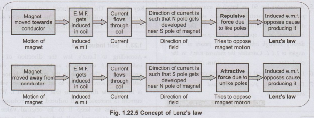
2) Lenz's Law :
This rule is based on the principles derived by German Physicist Heinrich Lenz.
The Lenz's law states that, 'The direction of
an induced e.m.f. produced by the electromagnetic induction is such that it
sets up a current which always opposes the cause that is responsible for
inducing the e.m.f.' In short the induced e.m.f. always opposes the
cause producing it, which is represented by a negative sign, mathematically in
its expression.
ஃ e = - N dϕ/dt
The
explanation can be given as below : Sud Consider a solenoid as shown in the
Fig. 1.22.4. Let a bar magnet is moved towards coil such that N-pole of magnet
is facing a coil which will circulate the current through the coil.

•
According to Lenz's Law, the direction of current due to induced e.m.f. is so
as to oppose the cause. The cause is motion of bar magnet towards coil. So
e.m.f. will set up a current through coil in such a way that the end of
solenoid facing bar magnet will become N-pole. Hence two like poles will face
each other experiencing force of repulsion which is opposite to the motion of
bar magnet as shown in the Fig. 1.22.4.
•
If the same bar magnet is moved away from the coil, then induced e.m.f. will
set up a current in the direction which will cause, the end of solenoid facing
bar magnet to behave as S-pole. Because of this two unlike poles face each
other and there will be force of attraction which is direction of magnet, away
from the coil. The galvanometer shows deflection in other direction.
The Lenz's law can be summarized as, show in
Fig. 1.22.5.
2. Statically Induced E.M.F.
Key Point :
The change in flux lines with respect to coil can be achieved without physically
moving the coil or the magnet. Such induced e.m.f. in a coil which is without
physical movement of coil or a magnet is called statically induced e.m.f.
• Explanation :
To have an induced e.m.f. there must be change in flux associated with a coil.
Such a change in flux can be achieved without any physical movement by
increasing and decreasing the current producing the flux rapidly, with time.
• Consider an electromagnet which is producing
the necessary flux for producing e.m.f. Now let current through the coil of an
electromagnet be an alternating one. Such alternating current means it changes
its magnitude periodically with time. This produces the flux which is also
alternating i.e. changing with time. Thus there exists dϕ / dt associated with
coil placed in the viscinity of an electromagnet. This is responsible for
producing an e.m.f. in the coil. This is called statically induced e.m.f.
Key Point :
It can be noted that there is no physical movement of magnet or conductor, it
is the alternating supply which is responsible for such an induced e.m.f.
The concept of statically induced e.m.f. is shown in the Fig. 1.22.6.

Such
an induced e.m.f. can be observed in case of a device known as transformer.
Key Point :
Due to alternating flux linking with the coil itself, the e.m.f. gets induced
in that coil itself which carries an alternating current.
The
statically induced e.m.f. is further classified as,
1)
Self induced e.m.f. and
2)
Mutually induced e.m.f.
Review Questions
1. Derive the
expression for the magnitude of the dynamically induced e.m.f.
AU : Dec.-16, 19,
Marks 8
2. Explain Fleming's
right hand rule.
3. Explain Lenz's
law.
4. A square coil of
20 cm side is rotated about its axis at a speed of 200 revolutions per minute in
a magnetic field of density 0.8 Wblm . If the number of turns of coil is 25,
determine maximum e.m.f. induced in the coil. (Ans. : 16.75 V)
5. A conductor has 50
cm length is mounted on the periphery of a rotating part of d.c. machine. The
diameter of a rotating drum is 75 cm. The drum is rotated at a speed of 1500
r.p.m. The flux density through which conductor passes at right angles is 1.1
T. Calculate the induced e.m.f. in the conductor. (Ans. : 32.397 volts)
6. Explain the
concept of statically induced e.m.f.
7. Explain clearly
the statically and dynamically induced EMFs. AU : Dec.-13,14,15, May-12, Marks
4
Electrical Machines: Unit I: a. Magnetic Circuits and Electromagnetism : Tag: : Dynamically, Statically - Nature of the Induced E.M.F.
Related Topics
Related Subjects

Electrical Machines I
EE3303 EM 1 3rd Semester EEE Dept | 2021 Regulation | 3rd Semester EEE Dept 2021 Regulation