Electrical Machines: Unit II: D.C. Generators
Necessity of Parallel Operation of Generators
DC Generators
The generating stations either of d.c. type or of a.c. type, normally consist of number of smaller generators operating in parallel instead of large single unit capable of supplying the maximum load demand. These smaller units can run in single or in various parallel combinations to supply actual load for following different reasons :
Necessity
of Parallel Operation of Generators
•
The generating stations either of d.c. type or of a.c. type, normally consist
of number of smaller generators operating in parallel instead of large single
unit capable of supplying the maximum load demand. These smaller units can run
in single or in various parallel combinations to supply actual load for
following different reasons :
1. Continuity and reliability of
service
The
most important requirement for any generator is its continuity. This cannot be
achieved if there is a single unit as in case of breakdown of prime mover or
generator, there will be total unavailiability of the supply. This also affects
the reliability of the supply. The requirement of uninterrupted supply is
important in case of industrial loads as otherwise the economy may get
affected. Thus instead of having a single large unit, number of small
generators are operated in parallel.
2. Maintenance and repair
It
is required to have a periodic checking and inspection of prime mover and
generator to avoid the possibility of total breakdown or shunt down in future.
If any of generators in under maintenance or repair then the load on that
generator can be shared by other generators as all of them are working in
parallel. Thus in case of failure or breakdown in any of the generators, the
generator can be repaired with more care as other generators are available to
maintain the service.
3. Efficiency
The
load on the generating station is never constant. It varies from time to time
with maximum demand occuring during morning and evening while minimum demand
during late night hours. Most of the generators operate efficiently when
delivering the full load. Thus when there is light load condition, it is
economical to use a small, single unit. With increase in load demand, a large
generator may be put in service instead of a smaller one or another smaller
unit may be connected in parallel with the earlier unit which is already in
service.
4. Increase in plant capacity
Additional generators are always installed in
existing plant to supply increasing load demands. Provision for the future
expansion is made from the begining itself. If number of generators are
operating in parallel then it is easier to add other generators for parallel
operation with increase in load demand.
1. Parallel Operation of D.C. Generators
•In
case of d.c. gnenrating stations, there are heavy thick copper bars which act
as positive ans negative terminals for the entire stations. These bars are called
bus bars. While connecting the d.c. generators in parallel, the positive and
negative terminals of the generators should be respectively connected to the
positive and negative terminals of bus bars. If the generator is connected with
reverse polarity to the bars, it results in short circuit which will cause
damage to the commutators and brushes, ultimately shutting down the station.
Before making the parallel operation, it should be checked for reversed
polarity for the generators otherwise breakers are tripped off as a result of
heavy fault current.
•
Consider the bus bar with positive and negative terminals as shown in the Fig.
3.30.1. The generators are connected to these bus bars for parallel operation.
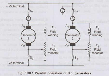
•
The generator 1 is connected to the bus bars and supplying to the load. Now
generator 2 is to be connected in parallel.
•
The prime mover of the generator 2 is started and its speed is adjusted to the
rated value. Then the switch S4 is closed. The voltmeter connected
across the open switch S2 completes the circuit. Now the excitation
of the generator 2 is adjusted with the help of field rheostat till the
voltmeter reads zero. The zero on the voltmeter ensures that the voltage of
incoming generator 2 is same as that of generator 1 or the bus bar voltage. The
switch S2 is then closed which connects the incoming generator 2 in parallel
with the system.
•
Under these conditions, the generator 2 will not take any load as its induced
emf is same as bus bar voltage and there will not be any flow of current
between two points at same potential. This generator is thus said to be
floating on bus bars.
•
In order that the generator 2 should supply current, it is necessary that its
induced emf should be more than the bus bar voltage. If E is induced emf and V
is bus bar voltage then the current current supplied I is given by,
I
= E-V / Ra
where Ra is resistance of armature winding
•
To increase the induced e.m.f. of incoming generator 2 its field is
strengthened till it takes proper share of load. At the same time the field of
generator 1 is weakened to maintain the bus bar voltage constant.
•
In short the following procedure should be adopted while paralleling the d.c.
generators :
1.
The generator which is to be connected in parallel is called incoming
generator. Start the prime mover of incoming generator and adjust it's speed to
rated value.
2.
Close the disconnected switch of the incoming generator.
3.
The excitation of the incoming generator is then adjusted till it is few volts
more than bus bar voltage.
4.
Close the breaker of the incoming generator.
5.
The shunt field rheostat of the incoming generator is adjusted to increase its voltage
while the field rheostats of already connected generators are adjusted to lower
their voltages till the desired load distribution which is indicated by
ammeters is achieved.
a. Conditions for Parallel
Operation of D.C. Generators
•
The necessary conditions for satisfactory parallel operation of d.c. generators
are,
1.
The polarities of the d.c. generators to be connected in parallel must be same.
2.
The variations in the voltage due to changes in the load should be of identical
characteristics.
3.
The voltages must be nearly identical so that each machine will contribute to
the load sharing.
4.
The prime movers driving the generators to be connected in parallel must have
similar and stable rotational speed characteristics.
2. D.C. Shunt Generators in Parallel
•
For stable parallel operation, the most suitable type of d.c. generator is
shunt generator as it has slightly drooping characteristics. If there is any
tendency for a generator to supply more or less than its proper share of load
then it changes system voltage which certainly opposes this tendency. This
restores the original division of load. Thus the shunt generators automatically
remains in parallel, once they are paralled.
• The Fig. 3.30.1 shows the two d.c. shunt generators connected in parallel.
•
If any of the generators is taken out of service then firstly its field is
weakened while the field of other generators is strengthened till the ammeter
associated with that generator reads zero. After this, the breaker and the
concerned switch are opened to take the generator out of service. This
procedure of connecting and disconnecting a generator from service prevents any
shock and sudden disturbances to the prime mover or the system itself.
•
If field of any generator is weakened beyond certain extent then power will be
delivered to it. It will then run as a motor in its original direction. The
prime mover associated with it will be thus driven due to the motoring action
of the generator.
•
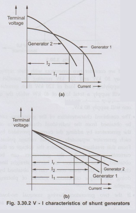
Consider voltage-current characteristics of a shunt generator as shown in the
Fig. 3.30.2 (a) and Fig. 3.30.2 (b).

•
Two shunt generators are considered. For common terminal voltage, the two
generators are supplying a current of I1 and 12
respectively. It can be seen that generator 2 has more dropping characteristics
and supplies less current.
•
The load will be divided properly within the two generators at all the points
provided their voltage characteristics are similar with each generator having
same voltage drop from no load to full load.
a. Load Sharing
•
If the two generators are having different kW ratings then they will share a
load in proportion to their ratings with their external characteristics plotted
with reference to percentage of full load current as shown in the Fig. 3.30.3.
•
If we consider two generators with their ratings as say 50 kW and 100 kW
running in parallel and supplying a total load of 120 kW then generator 1 will
supply a total load of 40 kW while the other one will supply 80 kW.
•
The combined characteristics of the generators can be obtained from the
individual characteristics of the generators by adding the currents provided by
each generator separately at equal voltage points. From this resultant
characteristics the voltage or the currents provided by the generators can be
obtained. If the generators are having straight line characteristics then these
results can be obtained by doing the simple calculations instead of plotting
graphs.
•
If the two generators having unequal no-load voltages are sharing a load then
its analysis is as given below
Let
E1 = No load voltage of generator 1
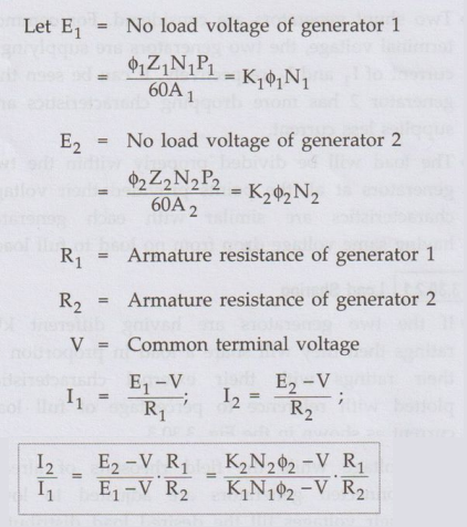
•
The bus bar voltage can be kept constant and the load can be transferred from
generator 1 to 2 by increasing either ϕ2 or N2 or by reducing N1
and ϕ1 change in N1 and N2 can be achieved by
changing the speeds of prime movers while by changing the shunt field rheostats
the fluxes ϕ1 and ϕ2 can be varied.
•
In summary it should be kept in mind that two shunt generators in parallel
having no load voltages equal will share the load in such a ratio that the load
current of each machine produces the same drop in each generator. If the
generators are having unequal no-load voltages and operated in parallel then
the load currents should produce sufficient voltage drops in each generator so
as to keep the terminal voltage same. The generator having lower voltage drop
takes more share of change in load. If the generators are working in parallel
and having different power ratings but same voltage regulation will divide the
load in proportion to their power ratings.
3. D.C. Series Generators in Parallel
•
Consider two d.c. series generators in parallel as shown in the Fig. 3.30.4.
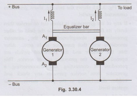
•
If no load voltages E1 and E2 of the two generators are
initially same, generators supply equal currents aand have equal resistance for
its field winding. If E1 > E2 then I1 >
I2 which causes the field of generator 1 strengthened while that of
2 is weakend which will decrease E2 further. A stage is reached
where generator 1 will take entire load and will also supply power to generator
2 which will start running as a motor. The two machines will form a short
circuited loop which will increase the current indefinitely. This can be
avoided by use of equalizer bar through which equal currents are passed in the
two similar generators to the load. The slight difference in the currents
therefore being confined to the loop made by the armatures and the equalizer
bar.
4. D.C. Compound Generators in Parallel
•
Consider two compound generators 1 and 2 running in parallel as shown in the
Fig. 3.30.5.
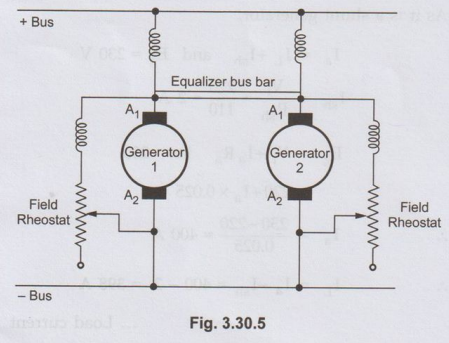
•
As the voltage characteristics for the usual compound generators are rising,
their parallel operation is unstable in the absence of corrective devices.
•
Let us consider that each generator is taking proper share of load. If for some
reason, the generator 1 takes increased load slightly then the current passing
through it's series field winding increases strengthening it's field to
increase the generated emf. This causes generator 1 to take still more load. If
system load is assumed to be constant then the load on generator 2 will
decrease weakening its series field due to less current passing through its
field winding which results in further decrease in its load. This effect is
cumulative which leads generator 1 to take the entire load and generator 2 will
be driven as motor. The circuit breakers of at least one of the two generators
will open to stop the parallel operation. The under compound generators show
stable operation like shunt generators.
•
For stable parallel operation of over and level compound generators, equalizer
bus bars are used. It is connected to the armature ends of the series coils of
the generators. The equalizer bus bar is also a conductor which is not required
is case of under compound generators as their characteristics are not rising.
•
Now consider that the same two compound generators are operating in parallel
with equalizer bar between them. If for any reason, generator 1 starts taking
more load than it's proper share then it's series field current is increased.
But now this increased field current will partly pass through series field
winding of generator 1 and partly through series field winding of generator 2
via equalizer bar. Thus the two generators are affected in similar way
preventing generator 1 from taking extra load. To have proper division of load
from no load to full load is required that the regulation of each generator
must be same. The series field resistances should be inversely proportional to
the generator ratings.
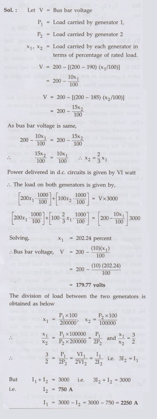
Ex. 3.30.1 Two shunt generators each with a
no load voltage of 200 V are run in parallel. Their external characteristics
can be taken as straight lines over this operating ranges. Generator No. 1 is
rated at 200 kW and its full load voltage is 190 V. Generator No. 2 is rated at
100 kW at 185 V. Calculate the bus bar voltage when the total load is 3000 A.
How is the load divided between the two ?
Sol. :
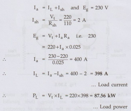
Ex. 3.30.2 A d.c. shunt generator is supplying load connected to a bus bar voltage of 220 V. It has an armature resistance of 0.025Ω and field resistance of 110 9. Calculate the value of load current and load power when it generates an e.m.f. of 230 V. Neglect the effect of armature reaction. Draw circuit diagram.
Sol. :
The
generator connected to the busbar is shown in the Fig. 3.30.6.
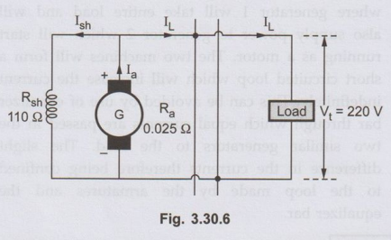
The
busbar voltage is the terminal voltage Vt = 220 V and the load is connected to
the busbar carrying current IL supplied by the generator.
At
it is a shunt generator,
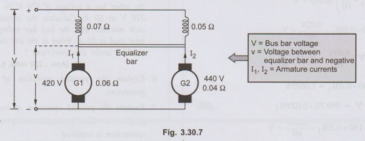
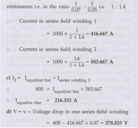
Ex. 3.30.3 Two d.c. compound generators are operating in parallel with an equalizer-bar coonection. Both machines are supplying a load of 1000 A. The machines have armature resistances of 0.06 Ω and 0.04 Ω, series-field resistances of 0.07Ω and 0.05 Ω and induced emfs of 420 V and 440 V respectively. Calculate: a) Current in each armature b) Current in each series-field winding c) Current in the equalizing-bar. d) Bus-bar voltage
Sol.
The arrangement is shown in the Fig. 3.30.7.
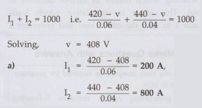
b)
The total current 0f 1000 A divide
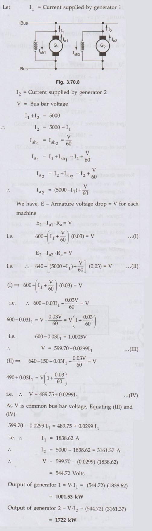
Ex. 3.30.4
Two shunt wound d.c. generators connected
in parallel to supply a load of 5000 A. Each machine has an armature resistance
of 0.03 Ω and field resistance of 60 Ω but the emf of one
machine is 600 V and that of other is 640 V. What power does each machine
supply?
Sol.:
Let
Review Questions
1. What are the
reasons for the parallel operation of d.c. generators?
2. What are the
conditions necessary for parallel operation of d.c. generators?
3. Explain the
conditions under which two shunt generators operating in parallel share the
total load in exact proportion to the machine ratings.
4. Why shunt generators are more suitable for
parallel operation.
5. Two 200 V d.c. generators each having linear external characteristics, operate in parallel. One load and 220 V at a load current of 40 A, while the other has a voltage of 270 V on no load and 220 V at 50 A. Calculate the output current of each machine and the bus bar voltage when the total load is 70 A. What is the kW output of each machine under this conditions ?
[Ans.: 230 volts, 6.9 kW, 9.2 kW]
6. Explain the
parallel operation of d.c. series generators.
7. Explain the
parallel operation of two compound generators. Clearly explain why an equalizer
connection is required.
Electrical Machines: Unit II: D.C. Generators : Tag: : DC Generators - Necessity of Parallel Operation of Generators
Related Topics
Related Subjects

Electrical Machines I
EE3303 EM 1 3rd Semester EEE Dept | 2021 Regulation | 3rd Semester EEE Dept 2021 Regulation