Electron Devices and Circuits: Unit IV: Multistage and Differential Amplifiers
Neutralization Methods
Tuned Amplifiers
• In tuned RF amplifiers, transistors are used at the frequencies nearer to their unity gain bandwidths (i.e. fT), to amplify a narrow band of high frequencies centred around a radio frequency.
Neutralization Methods
•
In tuned RF amplifiers, transistors are used at the frequencies nearer to their
unity gain bandwidths (i.e. fT), to amplify a narrow band of high frequencies
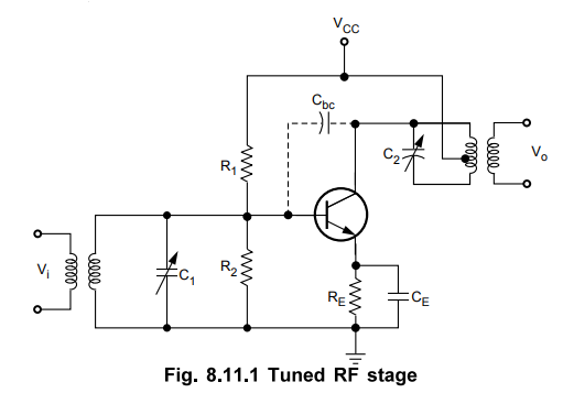
centred around a radio frequency. At this frequency, the inter junction
capacitance between base and collector, Cbc of the transistor becomes dominant,
i.e. its reactance becomes low enough to be considered, which is otherwise
infinite to be neglected as open circuit. Being CE configuration capacitance
Cbc, shown in the Fig. 8.11.1. come across input and output circuits of an
amplifier. As reactance of Cbc at RF is low enough it provides the feedback
path from collector to base. With this circuit condition, if some feedback signal
manages to reach the input from output in a positive manner with proper phase
shift, then there is possibility of circuit converted to an unstable one,
generating its own oscillations and can stop working as an amplifier. This
circuit will always oscillate if enough energy is fed back from the collector
to the base in the correct phase to overcome circuit losses. Unfortunately, the
conditions for best gain and selectivity are also those which promote
oscillation. In order to prevent oscillations in tuned RF amplifiers it was
necessary to reduce the stage gain to a level that ensured circuit stability.
This could be accomplished in several ways such as lowering the Q of time
circuits; stagger tuning, loose coupling between the stages or inserting a 'loser'
element into the circuit. While all these methods reduced gain, detuning and Q
reduction had detrimental effects on selectivity. Instead of loosing the
circuit performance to achieve stability, the professor L.A. Hazeltine
introduced a circuit in which the troublesome effect of the collector to base
capacitance of the transistor was neutralized by introducing a signal which
cancels the signal coupled through the collector to base capacitance. He proved
that the neutralization can be achieved by deliberately feding back a portion
of the output signal to the input in such a way that it has the same amplitude
as the unwanted feedback but the opposite phase. Later on many neutralizing
circuits were introduced. Let us study some of these circuits.
1. Hazeltine Neutralization
•
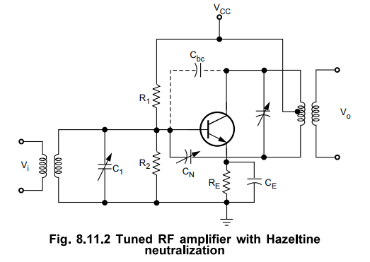
The Fig. 8.11.2 shows one variation of the Hazeltine circuit. In this circuit a
small value of variable capacitance CN is connected from the bottom of coil,
point B, to the base. Therefore, the internal capacitance C'bc' shown dotted,
feeds a signal from the top end of the coil, point A, to the transistor base
and the CN feeds a signal of equal magnitude but opposite polarity from the
bottom of coil, point B, to the base. The neutralizing capacitor, CN, can be
adjusted correctly to completely nullify the signal fed through the Cbc.
2. Modifield Hazoltine (Neutrodyne)
•
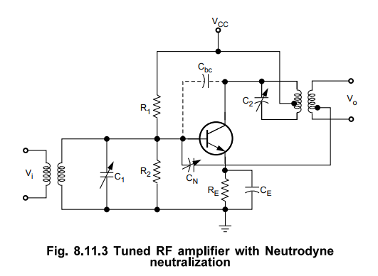
The Fig. 8.11.3 shows typical neutrodyne circuit. In this circuit the
neutralization capacitor is connected from the lower end of the base coil of
the next stage to the base of the transistor.
•
In principle, this circuit functions in the same manner as the Hazeltine
neutralization circuit with the advantage that the neutralizing capacitor does
not have the supply voltage across it.
3. Neutralization using Coil
•
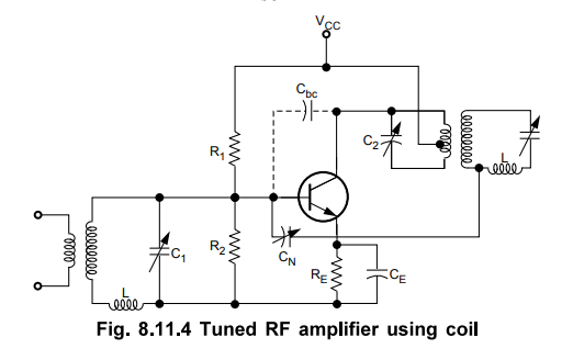
The Fig. 8.11.4 shows the neutralization of RF amplifier using coil. In this
circuit, L part of the tuned circuit at the base of next stage is oriented for
minimum coupling to the other windings. It is wound on a separate form and is
mounted at right angles to the coupled windings. If the windings are properly
polarized, the voltage across L due to the circulating current in the base
circuit will have the proper phase to cancel the signal coupled through the
base to collector, Cbc capacitance.
Review Questions
1. What is neutralization ?
2. Discuss briefly about neutralization in tuned amplifiers.
3. What is the need for neutralization ?
AU : ECE : May-06, Dec.-07, 08, 10, Marks 6
4. Discuss instability of tuned amplifier.
AU : ECE : May-08, Marks 4
5. Describe any one method of neutralisation used in tuned
amplifiers.
6. Why neutralization is used in tuned amplifiers?
AU : ECE : Dec.-09, Marks 2
7. Explain Hazeltine neutralization.
AU : ECE : May-06, 09, 10, 11, Marks 6
8. Explain Hazeltine neutralization method to maintain stability
in tuned amplifiers.
AU : ECE : Dec.-06, May-08, Marks 6
9. Indicate how coil neutralization technique is implemented in tuned
amplifiers.
AU : ECE : May-04, 09, 11, Marks 2
10. What is narrowband neutralization ?
AU : ECE : May-11, Marks 2
11. Draw the circuit
for narrowband neutralization.
AU : ECE : Dec.-10, Marks 2
12. Explain, with necessary circuits, 1) Hazeltine neutralization
and 2) Coil neutralization.
AU : ECE : Dec.-ll, Marks 8
13. With a neat circuit diagram, explain the Hazeltine method of neutralization.
Electron Devices and Circuits: Unit IV: Multistage and Differential Amplifiers : Tag: : Tuned Amplifiers - Neutralization Methods
Related Topics
Related Subjects

Electron Devices and Circuits
EC3301 3rd Semester EEE Dept | 2021 Regulation | 3rd Semester EEE Dept 2021 Regulation