Electric Circuit Analysis: Chapter - 1: Basic Circuit Analysis - DC
Nodal Method
Statement, Circuit Diagram, Formula, Solved Example Problems
The nodal method is used to analyze multi source circuits. In this method, we solve the simultaneous equations using Kirchhoff's current law (KCL) applied at various nodes in an electric circuit.
NODAL METHOD
20-200.1-8071-1-
The
nodal method is used to analyze multi source circuits. In this method, we solve
the simultaneous equations using Kirchhoff's current law (KCL) applied at
various nodes in an electric circuit. Node is defined as junction or joining
point of two or more component terminals.
In
nodal method, we select one node as a reference mode, with respect to the voltages
at all other nodes are measured. Thus, the reference node acts as a ground or
common for the circuit.
The
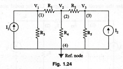
first step in nodal method is to convert all voltage sources to current
sources. The second step is to identify all the principal nodes in the circuit
and to choose a reference node. The choice is arbitrary, but it is usually
convenient to select the reference node as the one having the most of the
components connected to it. All the nodes except the reference node are then
numbered and their corresponding voltages are designated as V1, V2...
etc. The reference node and other nodes are indicated as shown in circuit.
Steps
1.
Select one major node as the reference node and assign each of the (n-1)
remaining nodes with its own unknown potential (with respect to the reference
node).
2.
Assign branch current to each other branch.
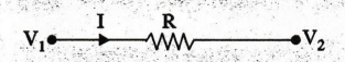
The
arrow is drawn from V1 towards V2 because current always
flows from higher potential to the lower potential.
3.
Express the branch currents in terms of the node potentials.
I
= V1 - V2 / R
4.
Write the current equation at each of the (n - 1) unknown nodes.
5.
Substitute the current expressions (Step-3) into the current equations
(Step-4), which then become a set of simultaneous equations of unknown node
voltages.
6.
Solve for the unknown voltages and the branch currents.
We
shall consider the circuit shown in figure 1.25 for nodal analysis.
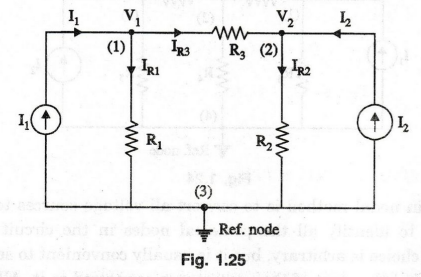
In
many circuits the reference node is most conveniently chosen as a common
terminal or the ground terminal. The above circuit diagram consists of three
nodes. It is possible to write (n - 1) equations for the circuit having 'n'
nodes. Applying KCL at node 1 gives
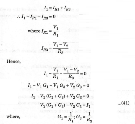
Next
consider node 2,
We
get I2 + IR3 - IR2 = 0
which
in terms of node voltages and resistances
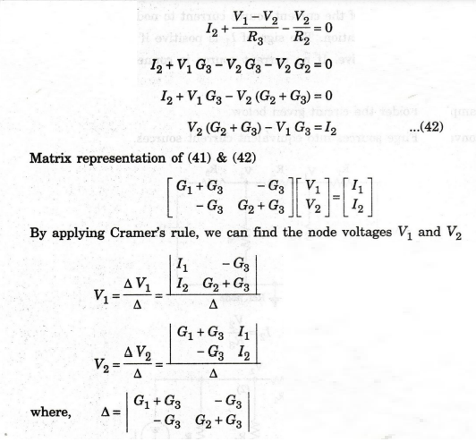
The
generalised node equations can be written as
[G]
[V] = [ I] ...(43)
where
the square matrix G is called the node conductance matrix, V is the column
matrix of the node voltages with respect to the reference node and I is the
column matrix of input currents.
Nodal
equations by inspection method
The
following steps are used in writing the node equations in matrix form.
Step
1:
First, convert all the voltage sources to equivalent current sources.
Step
2:
The conductances of all branches connected to node 1 are added and denoted by G11
G11 is called the self conductance of node 1.
Step
3: All
the conductances connected to nodes 1 and 2 are added and denoted by G12.
G12 is called mutual conductance of node 1 and 2. This G12
is written with negative sign. If no conductance is connected between nodes 1
and 2, then G12 = 0, G12 = G21.
Step
4:
I1 denotes the value of the current source current to node 1 and is
written on the right hand side of the equation. The sign of I, is positive if
it is flowing towards node I1, otherwise it is negative. If no
current source is connected to node 1, then
I1
= 0.
For
example, consider the circuit given below.
First
convert voltage sources into equivalent current sources.
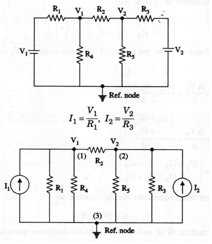
This
circuit consists of two nodes 1 and 2 and common (ref) node.
At node 1,
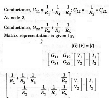
By
solving this matrix, we can find out nodal voltages V1, and V2.
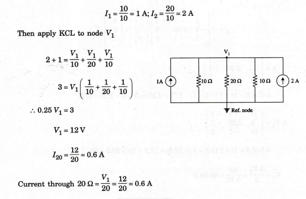
EXAMPLE
100:
Using nodal analysis, determine the current in the 20 Ω resistor.
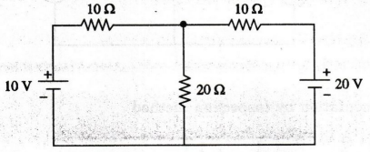
Solution
:
Convert all the voltage sources into their equivalent current sources.
EXAMPLE
101:
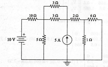
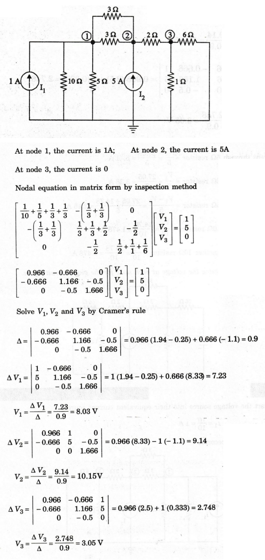
Find V1, V2, V3 by the nodal method for the
given circuit.
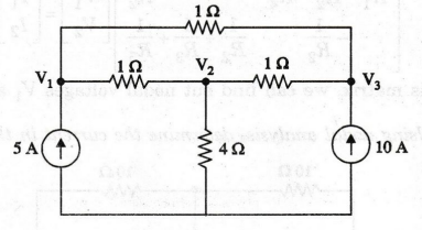
Solution:
Matrix
representation by inspection method
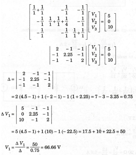
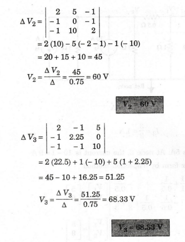
V1 = 66.66 V
EXAMPLE
102:
Find the voltages of the nodes 1 and 2 in the network shown in figure by
nodal method.
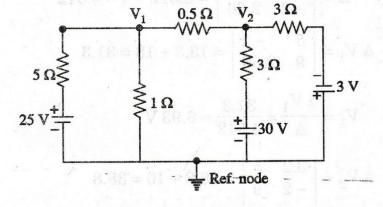
Solution:
Convert
all the voltages sources into their equivalent current sources.
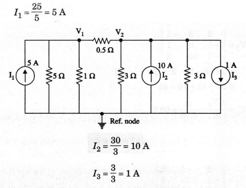
At
node 1, the current is 5A. At node 2, the current is 10 - 19 A
Nodal
equation in matrix form by inspection method
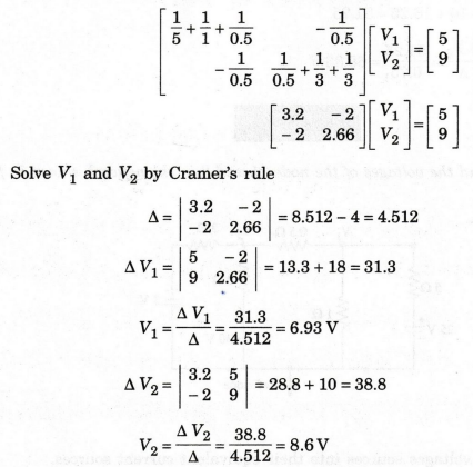
V1
= 6.93 V
V2
= 8.6 V
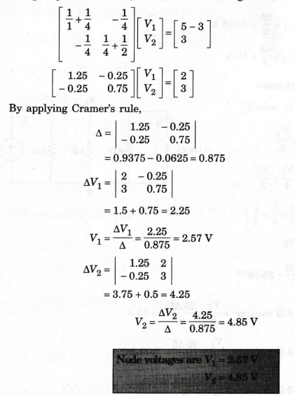
EXAMPLE 103: In the circuit of figure, find the node voltages V1 and V2.
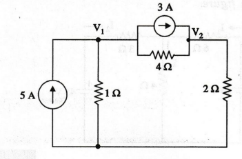
Solution:
Using
inspection method, the matrix form for given network is given by
EXAMPLE
104:
Using nodal analysis, obtain the currents flowing in all the resistors of
the circuit shown in figure.
Solution
:
Convert
all the voltage sources into their equivalent current sources.
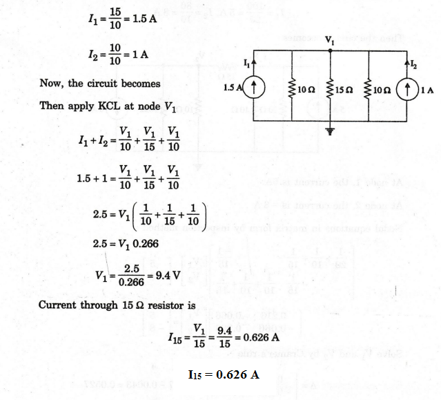
EXAMPLE
105:
Find the current through 15 2 resistor in the network shown in figure by
nodal method.
Solution
:
Convert
all the voltage sources into their equivalent current sources.
EXAMPLE
106:
Calculate the voltage across the 152 resistor in the network shown in figure
below using nodal analysis.
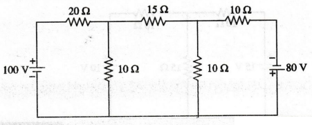
Solution:
Convert
all the voltage sources into their equivalent current sources.

EXAMPLE
107: Find the current through 2 2 resistor
in the network using loop current analysis and node voltage analysis.
(AU/CSE - Dec 2004)
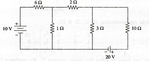
Solution:
Loop
current analysis
First,
we should mark current direction in this network. Refer the figure shown below.
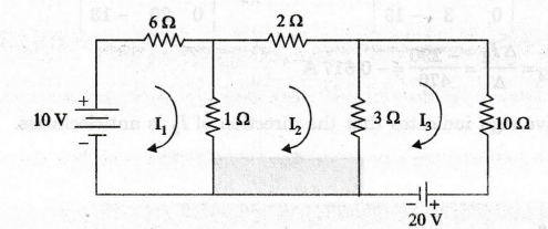
Let
us assume three mesh currents, I1, I2 and I3
as shown in figure.
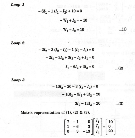
Here,
we have to solve the mesh current 12. By applying Cramer's rule, we can easily
find out mesh current.
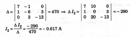
The
negative sign indicates that the direction of I2 is anticlockwise.
I2
= 0.617 A
Nodal
Analysis
Convert
all the voltage sources into their equivalent current sources.
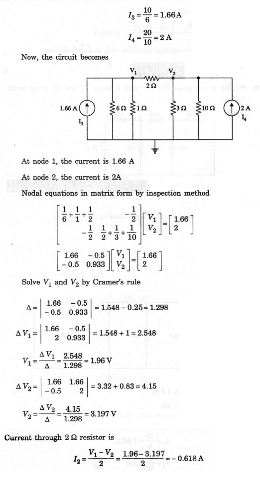
The
negative sign indicates the current direction of 12 is anticlockwise
I2
= - 0.618 A
EXAMPLE
108: For the circuit given find the node voltages V1 and V2 using nodal
analysis.
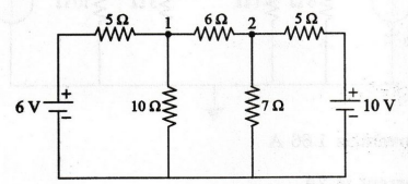
Solution
:
Convert
all the voltage sources into their equivalent current sources.
I1
= 6/5 = 1.2 A
I2
= 10/5 = 2 A
Then,
the circuit becomes
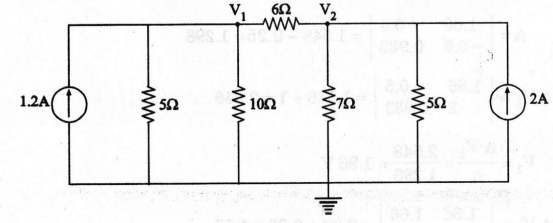
At
node 1, the current is 1.2 A
At
node 2, the current is 2A
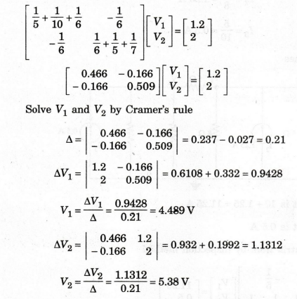
Node
equations in matrix form by inspection method
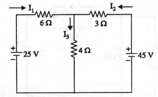
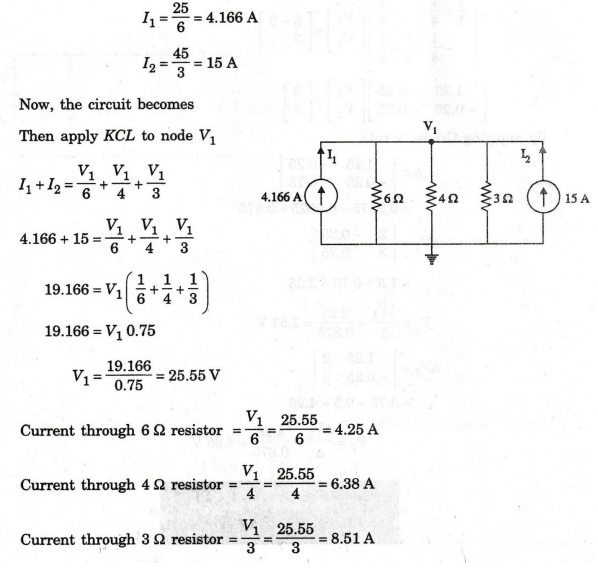
EXAMPLE
109: For the circuit of figure, find the current in each
branch by nodal method.
Solution
:
Convert
all the voltage sources into its equivalent current sources.
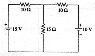
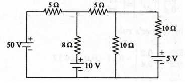
EXAMPLE
110:
Determine the voltage at each node for the given circuit figure.
Solution :
Convert
the voltage source into their equivalent current source
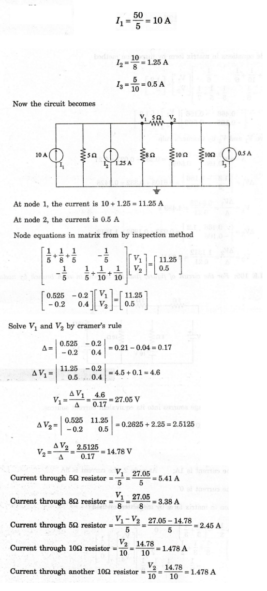
I2
= 10 / 10 = 1 A
Now
the circuit becomes
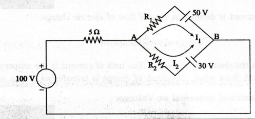
EXAMPLE
111:
In the circuit shown in figure, what are the values of R1 and R2,
when the current flowing through R1 is 1A and R2 is 5A?
What is the value of R2 when the current flowing through R1
is zero?
Solution
:
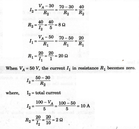
The
current in the 5Ω resistance I5 = I1 + I2 = 1+ 5 = 6A
Voltage
across 5 Ω, V5 = 5 × 6 = 30 V
The
voltage at node A, VA = 100 - 30= 70 V
Electric Circuit Analysis: Chapter - 1: Basic Circuit Analysis - DC : Tag: : Statement, Circuit Diagram, Formula, Solved Example Problems - Nodal Method