Electromagnetic Theory: Unit V: Electromagnetic Waves
Oblique Incidence of Uniform Plane Waves
Electromagnetic Waves
• When a uniform plane wave strikes obliquely on the surface (either conductor or dielectric), the behaviour of the reflected wave is decided by the polarization of the incident wave. There are two cases for the oblique incidence as given below.
Oblique Incidence of Uniform Plane Waves
AU
: June-07, Dec.-lO, 13,14
•
When a uniform plane wave strikes obliquely on the surface (either conductor or
dielectric), the behaviour of the reflected wave is decided by the polarization
of the incident wave. There are two cases for the oblique incidence as given
below.
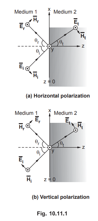
Case
(i) : The electric field vector perpendicular to the
plane of incidence. In other words, the electric field vector is aligned
parallel to the boundary surface as shown in the Fig. 10.11.1 (a). This is
called horizontal polarization.
Case (ii) : The magnetic field vector is aligned parallel to the boundary surface. In other words, the magnetic field vector is perpendicular to the plane of incidence while the electric field vector is aligned parallel to the plane of incidence as shown in the Fig. 10.11.1 (b). This is called vertical polarization.
•
It is seen that, in both the cases, a new term 'plane of incidence' is used.
What is meant by plane of incidence?
Key Point : A plane of incidence is a plane containing the vector in the direction of propagation of the incident wave and the normal to the boundary surface.
•
The horizontal and vertical polarizations, illustrating two special cases are
as shown in the Fig. 10.11.1 (a) and (b).
•
Before we actually start discussing the different conditions for oblique
incidence, let us take a review of most convenient way of expressing a uniform
plane wave interms of direction cosines of the normal to the plane containing
the wave.
1. Direction Cosines
•
According to the definition of a uniform plane wave, the wave for which the
equiphase surface is a plane.
• In general, any wave travelling in z-direction
can be expressed in phasor form as

•
For a wave travelling in positive z-direction, given by equation (10.11.1), the
equiphase plane is given by equation,
z
= a constant
•
For a uniform plane wave travelling in any arbitrary direction, the equiphase
surfaces can be obtained by replacing z with some expression. Thus the equation
of a plane is given by,

•
Let a uniform plane wave be travelling in some arbitrary direction say d. Let ![]() be the unit vector normal to the plane P as shown in the Fig. 10.11.2. In the
Fig. 10.11.2, positive x, y, z axes are considered. Also the plane which is
perpendicular to
be the unit vector normal to the plane P as shown in the Fig. 10.11.2. In the
Fig. 10.11.2, positive x, y, z axes are considered. Also the plane which is
perpendicular to ![]() , appears as a line P-P.
, appears as a line P-P.

•
We know that the projection of any vector in its normal direction is the dot
product of that vector with unit vector in the normal direction. For all the points
on the plane P, the distance OB remains constant. That means we can write

•
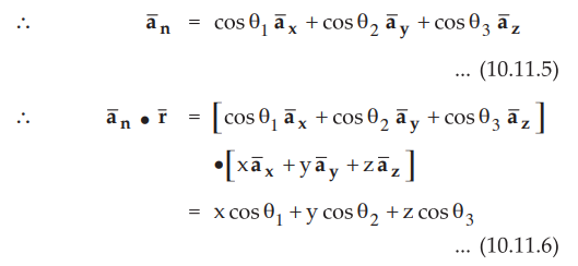
Let ![]() makes angles θ1 θ2 and θ3 with positive x, y and z axes
respectively so cos θ1, cos θ2 and cos
θ3
are the components of
makes angles θ1 θ2 and θ3 with positive x, y and z axes
respectively so cos θ1, cos θ2 and cos
θ3
are the components of ![]() along the positive x, y and z axes
respectively.
along the positive x, y and z axes
respectively.
•
Where cos θ1, cos θ2 and cos θ3
are called direction cosines of the vector.
•
Now the equation of a uniform plane wave travelling in the direction d (i.e. in
the direction of ![]() ) can be written as
) can be written as

2. Oblique Incidence at a Plane Conducting Boundary
•
Consider an interface between a perfect dielectric and perfect conductor. As we
have already studied that for oblique incidence there are two cases namely
horizontal polarization and vertical polarization. Let us consider these two
cases one by one.
a.
Horizontal Polarization
•
Consider that the plane wave is incident obliquely at the interface between a
perfect dielectric and a perfect conductor, with the electric field vector ![]() perpendicular to the plane of incidence as shown in the Fig. 10.11.3.
perpendicular to the plane of incidence as shown in the Fig. 10.11.3.
•
As ![]()

is perpendicular to the plane of incidence, this type of polarization is also called perpendicular polarization or E-polarization.
•
The unit vector in the direction of incident wave is ![]() . Let θi be the
angle of incidence. Then the unit vector is given by,
. Let θi be the
angle of incidence. Then the unit vector is given by,

•
Using the concept of direction cosines for equiphase surfaces, the equation of
the incident wave can be written as

•
The equation for incident magnetic field is given by,

•
For the reflected wave, the unit vector in the direction of the reflected wave
is given by,

•
Where θr is the angle of reflection.
•
The electric field in the reflected wave is given by,

•
As the medium 2 is perfect conductor, there will be no transmission. Hence
according to the boundary condition, at the interface, z = 0, the total
electric field intensity must be equal to zero.
•
Thus at the interface, z = 0,

•
To have equation (10.11.13) valid for all the values of x, Er must be equal to
- Ej. At the same time, the phase terms of both the incident and reflected wave
must be same. Thus the required condition is θr = θi which is called Snell's
law of reflection.
•
With above conditions, equation (10.11.12) can be written as,

•
Now the total electric field intensity in medium 1, ![]() can be
obtained by adding equation (10.11.9) and equation (10.11.14).
can be
obtained by adding equation (10.11.9) and equation (10.11.14).

•
Similarly total magnetic field intensity in medium 1 can be obtained by adding
equation (10.11.10) and equation (10.11.15).

•
From equations (10.11.16) and (10.11.17), following conclusions can be drawn
for perpendicular polarization with oblique incidence.
1.
The y-component of ![]() , i.e. E1y and the x-component of
, i.e. E1y and the x-component of ![]() ,
i.e. H1x represent standing waves generated in the z-direction which
is normal to the boundary. These standing wave patterns can be recognized by
the terms sin β z and cosβ z, where βz = β1 cos θi i.e. phase in
z-direction in medium 1.
,
i.e. H1x represent standing waves generated in the z-direction which
is normal to the boundary. These standing wave patterns can be recognized by
the terms sin β z and cosβ z, where βz = β1 cos θi i.e. phase in
z-direction in medium 1.
2.
In the x-direction, both Eiy and Hlx are in phase with respect to time and
space. Thus the phase velocity in x-direction in medium 1 is given by,
3.
The amplitude of the wave varies with z in the x-direction, hence the wave
propagating in x-direction is a non-uniform plane wave.
b.
Vertical Polarization
•
Consider that the plane wave is incident obliquely at the interface between a
perfect dielectric and a perfect conductor, with the electric field vector ![]() parallel to the plane of incidence as shown in the Fig.
10.11.4.
parallel to the plane of incidence as shown in the Fig.
10.11.4.

•
As ![]() is parallel to the plane of incidence, it is also called
parallel polarization or H-polarization.
is parallel to the plane of incidence, it is also called
parallel polarization or H-polarization.
•
The definitions of unit vectors  along with angles 01 and 0 r are
the same as studied in E-polarization (or perpendicular polarization). From
Fig. 10.11.4 it is clear that now the electric field intensities in the
incident and reflected waves have components in x as well as z-directions. But
the magnetic field intensity in the incident and reflected waves have
components only in y-direction. Using the equations derived in earlier section,
for the incident waves, we can write,
along with angles 01 and 0 r are
the same as studied in E-polarization (or perpendicular polarization). From
Fig. 10.11.4 it is clear that now the electric field intensities in the
incident and reflected waves have components in x as well as z-directions. But
the magnetic field intensity in the incident and reflected waves have
components only in y-direction. Using the equations derived in earlier section,
for the incident waves, we can write,

•
Again at the interface, z = 0, the tangential component of the electric field
intensity must be zero. Note that, for parallel polarization, the tangential
component of the electric field intensity is only x-component. Thus adding only
x-components of the electric field intensity from equation (10.11.18) and
equation (10.11.20), we get,

•
Similarly, the total magnetic field intensity in medium can be obtained by
adding equations (10.11.19) and (10.11.21),

•
From equations (10.11.22) and (10.11.23), following conclusions can be drawn
for parallel polarization for oblique incidence.
1.
The x-component of  i.e. H1y represent standing waves generated in the z-direction.
Similar to the previous case of horizontal polarization, these standing wave
patterns are recognized by the terms sin β1z and cos β1z
.
i.e. H1y represent standing waves generated in the z-direction.
Similar to the previous case of horizontal polarization, these standing wave
patterns are recognized by the terms sin β1z and cos β1z
.
2.
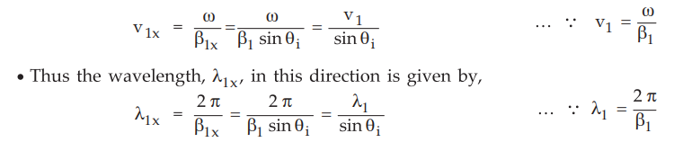
Both the components E1z and H1y are in phase with time and space in
x-direction. The velocity in this direction is given by,
v1x
= v1 / sin θi
Similarly
the wavelength of the wave in the same direction is given by,
λlx
= λ1 / sin θi
3.
The wave propagating in x-direction is a non-uniform plane wave.
3. Oblique Incidence at a Plane Dielectric Boundary
•
In the last section, we discussed the oblique incidence at a plane conducting
boundary. Now consider that a uniform plane wave is incident obliquely at the
interface between the two dielectrics. The two dielectric media are assumed to
be lossless with different constants. Such as µ2, Ɛ2 for
medium 1 while g2, e2 for medium 2. As the two media are having different
constitutive parameters, at the boundary, thus there is as if discontinuity.
Because of this, at the interface, a part of the incident wave is reflected;
while a part is transmitted as shown in the Fig. 10.11.5.

•
Let the lines OA, O'A' and O'B be the intersections of the plane of incidence
with the equiphase surfaces of the incident, reflected and transmitted waves
respectively. The incident and reflected waves travel in medium 1, while
transmitted wave in medium 2. The velocity for the waves in medium 1 is same
say v1. Then distances  must be same.

•
From equation (10.11.24) it is clear that the angle of incidence and angle of
reflection are equal. This is nothing but Snell’s law of reflection.
•
It is also observed the time taken by the incident wave to travel from A to O'
in medium 1 is equal to that taken by the transmitted wave to travel from O to
B in medium 2. Thus we can write,

•
Where v1 is the velocity of the wave in medium 1 while v2
is velocity of the wave in medium 2.

•
Simplifying above equation,

•
But for any medium, the ratio of the speed of light in free space to that in
medium is called index of refraction. It is denoted by n and it is given by,
n
= c / v
where
c = Velocity of light in free space
v
= Velocity of light in medium
•
Then for medium 1, index of refraction is given by,
n1
= c /v1
Similarly,
for medium 2, index of refraction is given by,
n2
= c /v2
•
Substituting values of v1 and v2 mterms of n1
and n2 in equation (10.11.25), we get,
sin θt / sin θi = n1/ n2
•
Equation (10.11.26) represents Snell’s law of refraction.
•
For a non-magnetic media, µ1 = µ2 = µ0.
•
Then we can write velocities as,
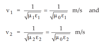
•
Putting the values v1 and v2 in equation (10.11.25), we
get,

•
Also we know, the intrinsic impedances for both the media are different. These
impedances can be expressed as follows.

•
Rearranging the terms in equation (10.11.27),

a. Total Reflection
•
Consider that medium 1 is denser as compared to medium 2 i.e. Ɛ1 > Ɛ2. Under
this condition the angle of transmission 91 becomes greater than the angle of
incidence. The angle of transmission 91 increases with angle of incidence θi.
When θt = π/2, the transmitted wave will be aligned along the
interface as shown in the Fig. 10.11.6.

•
If θi is increases further, then there will be no transmitted wave
and the condition is named as total reflection. The angle of incidence at which
the total reflection takes place is called critical angle (θc)
•
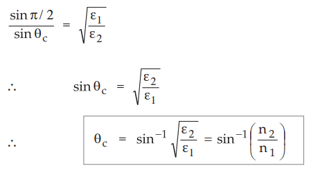
Then at θt = π/2, θi = θc, equation (10.11.27)
becomes,
Ex.
10.11.1 An electromagnetic wave from an underwater source with perpendicular
polarization is incident on a water air interface. Find critical angle θc if for fresh water Ɛr = 81, µr
= 1
Sol.
:
The critical angle is given by,

• From the discussion in the previous section,
it is clear that Snell's law of refraction and the critical angle calculation
are independent of type of polarizations. But to derive the formulae for the
transmission coefficient and reflection coefficient, we have to consider two
special cases of the polarizations namely horizontal (perpendicular)
polarization and vertical (parallel polarization).
b.
Horizontal Polarization (Perpendicular Polarization)
•
Consider that a uniform plane wave is incident obliquely with ![]() perpendicular to the plane of incidence as shown in the Fig. 10.11.7.
perpendicular to the plane of incidence as shown in the Fig. 10.11.7.

•
Using the concept of direction cosines, we can now easily write the field
intensity vectors in any medium.
•
The incident electric field intensity vector, in medium 1, is given by,

• Similarly the incident magnetic field intensity vector is given by,

From
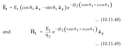
the Fig. 10.11.7, it is clear that a wave is transmitted in medium 2. Thus, in
medium 2, the field vectors are given as follows :

•
As we know, from boundary conditions, the tangential components of E and H must
be continuous at the interface, z = 0.
•
Thus for the electric field intensity ![]() and
and ![]() , we can write, at z = 0,
, we can write, at z = 0,

•
To have the phase matching for all x, the exponential factors which are
functions of x are equal in both the equations (10.11.36) and (10.11.37). This
requirement gives condition,
β1
x sinθi = β1 x sinθr = β2 x sinθt
...(10.11.38)
•
The condition stated above illustrates,
i)
Snell's law of reflection (θi = θr) and
ii)
Snell's law of refraction(sin θt / sin θi = β1 /
β2 )
Now
equation (10.11.36) can be written as,
Ei
+ Er = Et ... (10.11.39)
•
Similarly equation (10.11.37) can be written as,
1
/ ɳ1 (Ei - Er) cos θi = Et / ɳ2 cos θt
… (10.11.40)
• Simplifying equations (10.11.39) and (10.11.40), the transmission coefficient with perpendicular polarization is given by,

•
Similarly, the reflection coefficient, for perpendicular polarization is given
by,

Similar
to the condition for the normal incidence, for the oblique incidence we can
write,

c.
Vertical Polarization (Parallel Polarization)
•
Consider that a uniform plane wave, with Ē parallel to the plane of incidence,
is incident obliquely as shown in the Fig. 10.11.8.

•
The incident electric and magnetic field intensity vectors, in medium 1, are
given by,

….
(10.11.44)

•
Similarly for the reflected wave, the electric and magnetic field intensity
vectors are given by,

•
Now in medium 2, the transmitted electric and magnetic field intensity vectors
are given by,
•
Similar to the horizontal polarization, using boundary conditions, the
tangential components of ![]() and
and ![]() are continuous at the boundary.
are continuous at the boundary.
•
Thus we can write,

•
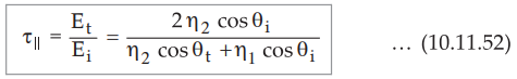
Solving equations (10.11.50) and (10.11.51), for the parallel polarization, the
transmission coefficient is given by,
•
Similarly, for parallel polarization, the reflection coefficient is given by,

•
From equations (10.11.52) and (10.11.53), the relation between τ||
and ɼ|| is given by,

•
The condition for no reflection occurs when τ|| = 0. Thus for no
reflection, the numerator in equation (10.11.53) must be zero, which gives

According
to Snell's law of refraction,

•
Where n1 and n2 are the refractive indices. Thus we can
write,

•
Here angle θi is called Brewster angle for parallel polarization and
it is denoted by θB. When θi = θB for parallel
polarization, no reflection takes place. For non-magnetic media only the
equation (10.11.56) is valid. For non-magnetic media µ1 = µ2. Then the no
reflection condition is modified as,

•
The alternative formula for the Brewster angle is given by,

Then
Brewster angle θB is given by,

•
The significance of Brewster angle is that, when an unpolarized wave is
incident obliquely at the Brewster angle θB, only the component with
perpendicular polarization will be reflected ; while component with parallel
polarization will not be reflected. Hence it is also referred as polarizing
angle.
Ex.
10.11.2 A parallel polarized wave propagates from air to a dielectric at
Brewster angle of 75°. Find Ɛr.
Sol.
:
A parallel polarized wave travels from air (medium-1) to a dielectric
(medium-2).
For
air, Ɛ1 = Ɛr1 Ɛ0 = Ɛ0 as Ɛ r1
=1
For
dielectric, Ɛ2 = Ɛr2 Ɛ0
Brewster
angle θB =75°
The
Brewster angle is given by,

Ex.
10.11.3 Determine the critical angle for the electromagnetic wave passing
through glass to air if er for glass is 9.
Sol.
:
Medium 1 is glass, for which Ɛr1 = 9 ; while medium 2 is air, for
which Ɛr2 = 1.
The
critical angle is given by,

Ex.
10.11.4 A uniform plane wave in air with  is incident on a dielectric
slab (z ≥ 0) with µr = 1.0, σ = 0. Ɛr = 2.5. find : a) Polarization of wave b)
The angle of incidence c) The transmitted
is incident on a dielectric
slab (z ≥ 0) with µr = 1.0, σ = 0. Ɛr = 2.5. find : a) Polarization of wave b)
The angle of incidence c) The transmitted ![]() field.
field.
AU
: June-07
Sol.
:
i) From the given expression of ![]() field , it is clear that, the propagation
vector is,
field , it is clear that, the propagation
vector is,

As
unit vector normal to interface at z = 0 is ![]() , the plane consisting
, the plane consisting  plane and it is a plane of incidence. As
 ![]() is normal to this plane,
the wave polarization is perpendicular polarization.
is normal to this plane,
the wave polarization is perpendicular polarization.
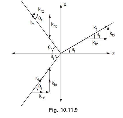
ii)
Let us refer following Fig. 10.11.9 which illustrates all propagation vectors.
From
Fig. 10.11.9.
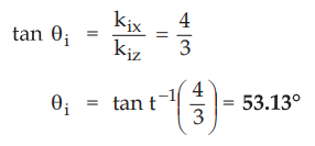
Thus
the angle of incidence is θi = 53.13°
iii)
Let us assume that the reflected electric field component be

Not
that ![]() unit vector indicates that the tangential component
unit vector indicates that the tangential component
of ![]() is continuous at interface.
is continuous at interface.
But
by property, θi = θr and ki = kr. Hence we
can write

Hence
the reflection coefficient for the perpendicular polarization is given by,

Thus
the transmission coefficient for perpendiculaqr polarization is given by,

Examples
for Practice
Ex.
10.11.5 An electromagnetic wave travelling in
free space is incident on a dielectric medium with relative permeability equal
to 2 at an angle of 45°. Find the angle bp which ![]() tilts as wave
crosses the boundary ?
tilts as wave
crosses the boundary ?
[Ans.:
30°]
Ex.
10.11.6 An EM wave travelling in a dielectric
medium having dielectric constant 9 is incident at an angle on the
dielectric-air interface.
Determine
:
i)
Critical angle ii) Reflection coefficient for perpendicular polarization. If
the angle of incidence is 15°.
[Ans.
: 19.47° 125.578 4.95° 0.744]
Ex.
10.11.7 A light is incident from air to glass
at Brewster’s angle. Determine the incident and transmitted angles.
[Ans.
: 71.565° 9i = 71.565 ° 18.434°
Review
Questions
1. Define Brewster angle and derive its expression.
AU : Dec.-10, 13, Marks 16
2. Define plane of incidence. Explain in brief direction
cosines.
3. What do we mean when we say that an incident wave has
a) Perpendicular polarization b) Parallel polarization.
4. Explain Snell's law of reflection and Snell's law of
refraction.
5. What is total reflection in case of oblique incidence at a
plane dielectric boundary ? What is critical angle θc ? Derive the express ion
for θc.
6. Derive the expressions for reflection coefficient and
transmission coefficient for a obliquely incident wave having
i) Perpendicular polarization
ii) Parallel polarization.
7. Write a note on Brewster angle.
8. Briefly explain about the wave incident obliquely to the
surface of perfect conductor.
AU : Dec.-14, Marks 8
Electromagnetic Theory: Unit V: Electromagnetic Waves : Tag: : Electromagnetic Waves - Oblique Incidence of Uniform Plane Waves
Related Topics
Related Subjects

Electromagnetic Theory
EE3301 3rd Semester EEE Dept | 2021 Regulation | 3rd Semester EEE Dept 2021 Regulation