Linear Integrated Circuits: Unit II: Characteristics of Op-amp
Op-amp Current to Voltage Converter
Working Principle, Circuit Diagram, Applications, Solved Example Problems | Operational amplifier
Since A is measured in ohms, it is more appropriate to denote gain by the symbol R. Because of this, I-V converters are also called transresistance amplifiers.
Current to Voltage Converter
In
such a converter, the output voltage is proportional to the input current. It
accepts an input current I¡ and yields an output voltage Vo such
that Vo = A Ii, where A is the gain of the circuit. Since
A is measured in ohms, it is more appropriate to denote gain by the symbol R.
Because of this, I-V converters are also called transresistance amplifiers.
Fig.
2.26.1 shows the current to voltage converter.
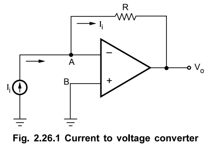
The node A is a virtual ground as node B is grounded.

Key
Point Thus, output voltage is proportional to the
input current and circuit works as a current to voltage converter.
This
circuit is also referred as Current Controlled Voltage Source (CCVS). If the
resistance in circuit is replaced by the impedance Z, the circuit is called
transimpedance amplifier.
1. Applications of I/V Converter
One
of the most frequent applications of I/V converters is in connection with
current type photodetectors such as photodiodes, photoFETs and
photomultipliers. Another common application is I/V conversion of current
output digital to analog converter. In this section we are going to study few
applications of I/V converters.
a.
Photodiode Detector
Fig.
2.26.2 shows the connection diagram of one of the most widely used photodetectors,
photodiode.

The
photodiode produces electrical current in response to incident light. This
current flows through R. The voltage across R, the output voltage is
proportional to the diode current.
b.
PhotoFET Detector
Fig.
2.26.3 shows another photodetector circuit with photoFET.
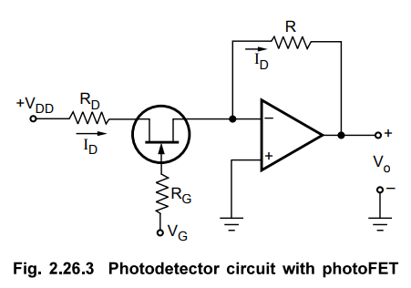
The photoFET is similar to a conventional junction FET, with the exception of a lens for focusing light onto the gate junction. On application of light, photons enter the gate area and excite valence electrons into the conduction band.
The
photon-excited current carriers cause a small current ∆
IG resulting in large current change ∆ ID The change in
ID results change the voltage drop across R and hence the output voltage.
Therefore the op-amp circuit acts as an I/V converter and gives the indication
of light interms of voltage.
Review Question
1. With the help of circuit diagram explain the operation of I
to V converter and its applications.
May-13, Dec.-15, Marks 8
Linear Integrated Circuits: Unit II: Characteristics of Op-amp : Tag: : Working Principle, Circuit Diagram, Applications, Solved Example Problems | Operational amplifier - Op-amp Current to Voltage Converter
Related Topics
Related Subjects

Linear Integrated Circuits
EE3402 Lic Operational Amplifiers 4th Semester EEE Dept | 2021 Regulation | 4th Semester EEE Dept 2021 Regulation