Linear Integrated Circuits: Unit II: Characteristics of Op-amp
Op-amp Ideal Inverting Amplifier
Working Principle, Derivation, Observations , Waveform, Circuit Diagram, Solved Example Problems | Operational amplifier
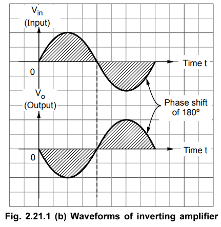
As the name suggests the output of such an amplifier is inverted as compared to the input signal. The inverted output signal means having a phase shift of 180o as compared to the input signal.
Ideal Inverting Amplifier
As
the name suggests the output of such an amplifier is inverted as compared to
the input signal. The inverted output signal means having a phase shift of 180o
as compared to the input signal.
So,
an amplifier which provides a phase shift of 180° between input and output is
called inverting amplifier.
The
basic circuit diagram of an inverting amplifier using op-amp is shown in the
Fig. 2.21.1 (a).

Derivation
of closed loop gain :
As
node B is grounded, node A is also at ground potential, from the concept of
virtual ground, so VA =0.
I
= Vin – VA / R1
I
= Vin / R1 ... (2.21.1)
Now from the output side, considering the direction of current I we can write,
I
= VA – Vo / Rf
I
= - Vo / Rf …. (2.21.2)
Entire
current I passes through Rf as op-amp input current is zero.
Equating
equations (2.21.1) and (2.21.2) we get,
Vin
/ R1 = Vo / Rf
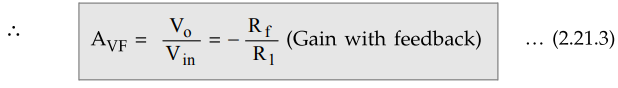
The Rf / R1 is the gain of the amplifier while negative sign indicates that the polarity of output is opposite to that of input. Hence it is called inverting amplifier.
The
input and output waveforms are shown in the Fig. 2.21.1 (b).
Observations
:
1.
The output is inverted with respect to input, which is indicated by minus sign.
2.
The voltage gain is independent of open loop gain of the op-amp, which is
assumed to be large.
3.
The voltage gain depends on the ratio of the two resistances. Hence selecting Rf
and R1, the required value of gain can be easily obtained.
4.
If Rf > R1, the gain is greater than 1.
If
Rf < R1, the gain is less than 1.
If
Rf = R1 the gain is unity.
Thus
the output voltage can be greater than, less than or equal to the input
voltage, in magnitude.
5.
If the ratio of R f and R1
is K which is other than one, the circuit is called scale changer while for Rf
/ R1 = 1 it is called phase inverter.
6.
The closed loop gain is denoted as AVF or AVCL i.e. gain
with feedback.
1. Sign Changer
In
the ideal inverting amplifier if Rf ≠ R1 then the gain is
ACL = -1 Thus the magnitude of output is same as that of the input
but its sign is opposite to that of the input.
Vo
= -Vin for Rf = R1
This
circuit is called sign changer or phase inverter.
2. Scale Changer
In
the ideal inverting amplifier if Rf ≠ R1 then the gain is
ACL = -K where K = Rf/R1. Thus the circuit is used to
multiply input by a constant K called scaling factor.
Vo
= -K Vin
Example 2.21.1 Determine the voltage gain of the op-amp circuit shown in the Fig. 2.21.2.

Solution:
From the Fig. 2.21.2, R1 = 10 k Ω, Rf = 47 k Ω
The
circuit is inverting amplifier.

The
gain is 4.7 and negative sign indicates phase shift i.e. inverting mode.
Example
2.21.2 A sine wave of 0.5 V peak voltage is applied to an
inverting amplifier using R1 = 10 k Ω, and Rf =
50 k Ω.
It uses the supply voltages of ± 12 V. Determine the output and sketch the
waveform.
If
now the amplitude of input sine wave is increased to 5 V, what will he the
output ? Is it practically possible ? Sketch the waveform.
Solution
: For
an inverting amplifier.
Gain
= Vo / Vin = - Rf / R1 = -50 / 10 =
-5
Now Vm = 0.5 V for the input hence,
(Vo)m
= (Vin)m × Gain = 0.5 × 5 = 2.5 V peak
The
input and output waveforms are inverted with respect to each other and are
shown in the Fig. 2.21.3 (a).
Now
Vm = 5 V for the input hence,
(Vo)m
= (Vin)m × Gain = 5 × 5 = 25 V peak
But
op-amp output saturates at ± 12 V i.e. at supply voltages used. So portion
above ± 12 V and below - 12 V will be clipped off from the output. So 25 V peak
output is not practically possible. The input and output waveforms are shown in
the Fig.2.21.3 (b)

In
both cases, there exists a phase shift of 180° between input and output
Review Questions
1. Draw the circuit of inverting amplifier using op-amp and
derive expression for its gain.
May-04, 18, Marks 4
2. With the circuit diagram explain the operation of a scale
changer.
3. An inverting amplifier using op-amp has R1 = 10 kΩ
and Rf = 47 kΩ. It is applied with 2 V peak to peak sine wave voltage waveform.
An a.c. voltmeter is used between the output terminal and ground to measure
output voltage. Calculate reading on the voltmeter. Assume supply voltages to
be ± 12 V.
[Ans.: 3.3234 V]
Linear Integrated Circuits: Unit II: Characteristics of Op-amp : Tag: : Working Principle, Derivation, Observations , Waveform, Circuit Diagram, Solved Example Problems | Operational amplifier - Op-amp Ideal Inverting Amplifier
Related Topics
Related Subjects

Linear Integrated Circuits
EE3402 Lic Operational Amplifiers 4th Semester EEE Dept | 2021 Regulation | 4th Semester EEE Dept 2021 Regulation