Linear Integrated Circuits: Unit II: Characteristics of Op-amp
Op-amp Ideal Non-inverting Amplifier
Working Principle, Derivation, Observations , Waveform, Circuit Diagram, Solved Example Problems | Operational amplifier
An amplifier which amplifies the input without producing any phase shift between input and output is called non-inverting amplifier.
Ideal Non-inverting Amplifier
An
amplifier which amplifies the input without producing any phase shift between
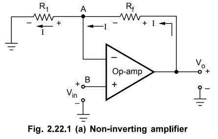
input and output is called non-inverting amplifier. The basic circuit diagram
of a non-inverting amplifier using op-amp is shown in the Fig. 2.22.1 (a). The
input is applied to the non-inverting input terminal of the op-amp.
Derivation
of closed loop gain :
The
node B is at potential Vin, hence the potential of point A is same
as B which is Vin, from the concept of virtual share.
VA
= VB = Vin … (2.22.1)
From
the output side we can write,
I
= Vo – VA / rf
I
= Vo – Vin / rf
… (2.22.2)
At
the inverting terminal,
I
= VA – 0 / R1 i,e.
I = Vin / R1 …
(2.22.3)
Entire
current passes through R1 as input current of op-amp is zero.
Equating
equations (2.22.2) and (2.22.3),

The
positive sign indicates that there is no phase shift between input and output.
The
input and output waveforms are shown in the Fig. 2.22.1 (b).

1. Comparison
The
Table 2.22.1 provides the comparison of the ideal inverting and non-inverting
amplifier op-amp circuits.

Observations
1.
The voltage gain is always greater than one.
2.
The voltage gain is positive indicating that for a.c. input, the output and
input are in phase while for d.c. input, the output polarity is same as that of
input.
3.
The voltage gain is independent of open loop gain of op-amp, but depends only
on the two resistance values.
4.
The desired voltage gain can be obtained by selecting proper values of Rf
and R1
Example
2.22.1 Determine the output voltage for the following
circuits.
May-04,
17, Marks 6.5

Solution
:
From the above Fig., it is non-inverting amplifier with Rf = 5 k
Ω,
R1 = 1 k Ω

Solution:
The circuit is shown in the Fig. 2.22.2

Gain
= 1+ R2 / R1
=
1+ 4.7×10³ / 470 = 11
Review
Questions
1.
Draw the circuit of noninverting amplifier using op-amp and derive expression
for its gain May-04, Marks 4
2.
For the op-amp configuration shown in the Fig. 2.22.3, determine the Rf if the gain required is 61.

Linear Integrated Circuits: Unit II: Characteristics of Op-amp : Tag: : Working Principle, Derivation, Observations , Waveform, Circuit Diagram, Solved Example Problems | Operational amplifier - Op-amp Ideal Non-inverting Amplifier
Related Topics
Related Subjects

Linear Integrated Circuits
EE3402 Lic Operational Amplifiers 4th Semester EEE Dept | 2021 Regulation | 4th Semester EEE Dept 2021 Regulation