Linear Integrated Circuits: Unit II: Characteristics of Op-amp
Op-amp Subtractor or Difference Amplifier
Working Principle, Circuit Diagram, Solved Example Problems | Operational amplifier
Similar to the summer circuit, the subtraction of two input voltages is possible with the help of op-amp circuit, called subtractor or difference amplifier circuit.
Subtractor or Difference Amplifier
Similar
to the summer circuit, the subtraction of two input voltages is possible with
the help of op-amp circuit, called subtractor or difference amplifier circuit.
The
circuit diagram is shown in the Fig. 2.28.1.

To
find the relation between the inputs and output let us use Superposition
principle.
Let
Vol be the output, with input V1 acting, assuming V2
to be zero.
And
Vo2 be the output, with input V2 acting, assuming V1
to be zero.
Case
1 :
With V2 zero, the circuit acts as an inverting amplifier. Hence we
can write, Vol = - (Rf / R1) V1 ... (2.28.1)
Case
2 :
While
with V1 as zero, the circuit reduces to as shown in the Fig. 2.28.2.

Let
potential of node B is VB.
The potential of node A is same as B i.e. VA = VB.
Applying
voltage divider rule to the input V2 loop

Equating
the equations (2.28.3) and (2.28.4)

Substituting
VB from equation (2.28.2) in equation (2.28.5) we get

Hence
using Superposition principle,

Now
if the resistances are selected as R1 = R2,

Key Point Thus the output
voltage is proportional to the difference between the two input voltages. Thus
it acts as a subtractor or difference amplifier.
If
R1 = R2 = Rf is selected,
Vo
= V2 – V1
But
by selecting proper values of R1 , R2 and Rf,
we can have the subtraction of two inputs with appropriate strengths like
Vo
= aV2 -b V1
Thus
using adders and subtractors, various mathematical equations like
Vo
= (aV1 + bV2) - (cV3 + dV4) can be
solved. In such equation, two adder circuits are used and the outputs of these
circuits are used as input to a subtractor to obtain the required equation.
Example
2.28.1 Design an op-amp circuit to give an output
voltage Vo = 4V1 -3V2 + 5V3 -V4.
Where V1, V2, V3 and V4 are inputs.
Solution
:
The positive and negative terms can be added seperately using two adders and
then subtractor can be used.
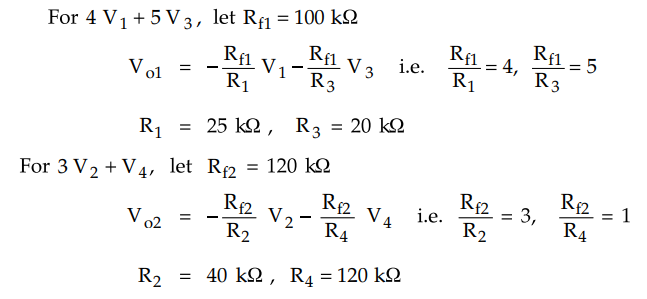
Use
the subtractor with all the resistances of same value of R = 100 kΩ.
Output
of the subtractor is Vo = Vo2 - Vo1
Vo
= - 3V2 -V4 - (- 4V1 - 5V3)= 4V1
- 3V2 + 5V3 - V4
The
designed circuit is shown in the Fig. 2.28.3

Example
2.28.2 Find V0 for the given circuit.
Dec.-08,
May-16, Marks 8

Solution
:
Use superposition principle.
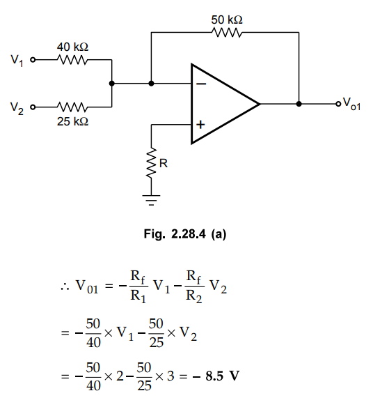
Case
1 :
Assume V1 and V2 acting and V3 and V4
= 0V
The
circuit works as inverting summer circuit, as shown in the Fig. 2.28.4 (a).
Case
2 :
Assume V3 acting and V1 = V2 = V4 =
0
The
circuit is as shown in the Fig. 2.28.4 (b). It acts as a noninverting
amplifier.

Case
3 :
Assume V4 acting and V1 = V2 = V3 =
0
The
circuit is as shown in the Fig. 2.28.4 (c).

Example
2.28.3 Design an adder-subtractor circuit for Vo
= 2V1 +5V2 -10V3.
Dec.-14,
Marks 6
Solution
: In
the first step, design adder to get 2V1 +5V2

The
circuit is shown in the Fig. 2.28.5 (a).

Generate
10 V3 using inverting amplifier.

Then
use subtractor to get Vo = Vo2 – Vo1

Use all resistances same for subtractor as 10 kΩ

Review Questions
1. Explain the differential amplifier using op amp.
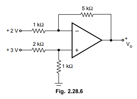
2. Calculate the output of the circuit shown in Fig. 2.28.6.
May-06, Marks 8
3. Draw an adder-subtractor type of circuit with op-amp to
obtain the relation V0 = (V1 + V2)- (V3+
V4).
Linear Integrated Circuits: Unit II: Characteristics of Op-amp : Tag: : Working Principle, Circuit Diagram, Solved Example Problems | Operational amplifier - Op-amp Subtractor or Difference Amplifier
Related Topics
Related Subjects

Linear Integrated Circuits
EE3402 Lic Operational Amplifiers 4th Semester EEE Dept | 2021 Regulation | 4th Semester EEE Dept 2021 Regulation