Linear Integrated Circuits: Unit II: Characteristics of Op-amp
Op-amp Symbol and Terminals
The op-amp is indicated basically by a triangle which points in the direction of the signal flow. All the op-amps have atleast following five terminals :
Op-amp Symbol and Terminals
The
symbol for an op-amp along with its various terminals, is shown in the Fig.
2.2.1.

The
op-amp is indicated basically by a triangle which points in the direction of
the signal flow.
All
the op-amps have atleast following five terminals :
i)
The positive supply voltage terminal VCC or + V.
ii)
The negative supply voltage terminal - VEE or - V.
iii)
The output terminal.
iv)
The inverting input terminal, marked as negative.
v)
The noninverting input terminal, marked as positive.
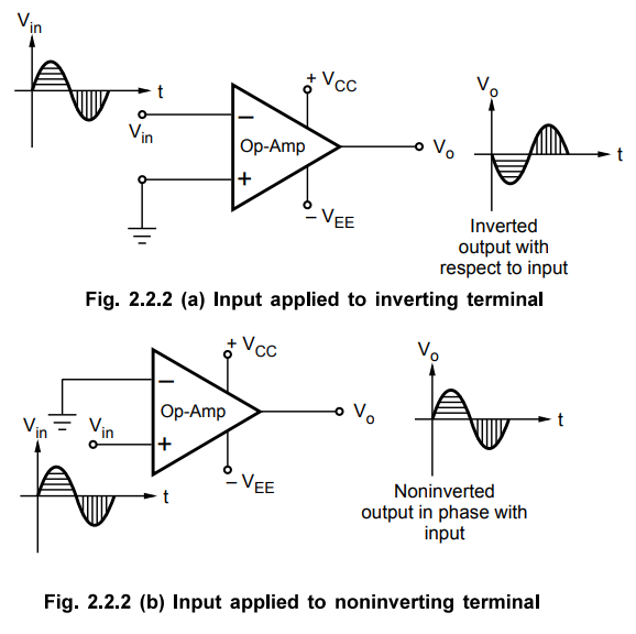
The
input at inverting input terminal results in opposite polarity (antiphase)
output. While the input at noninverting input terminal results in the same
polarity (phase) output. This is shown in the Fig. 2.2.2 (a) and (b). The input
and output are in antiphase means having 180° phase difference in between them
while inphase input and output means having 0° phase difference in between
them.
The
op-amp is fabricated on a tiny silicon chip and packaged in a suitable case.
Fine gauge wires are used to connect the chip to the external leads.
The
op-amp works on a dual supply. A dual supply consists of two supply
voltages both d.c., whose middle point is generally the ground terminal.
The dual supply is generally balanced i.e. the voltages of the positive supply +Vcc and that of the negative supply - VEE are same in magnitude. The typical commercially used power supply voltages are ± 15 V. But if the two voltage magnitudes are not same in a dual supply it is called as unbalanced dual supply. The balanced and unbalanced types of dual supply are shown in the Fig. 2.2.3 (a) and (b) respectively.

Practically
in most of the op-amp circuits balanced dual supply is used. The other popular
balanced dual supply voltages are ± 9 V, ± 12 V, ± 22 V etc.
Review Question
1. Draw the op-amp symbol and explain the various op-amp terminals.
Linear Integrated Circuits: Unit II: Characteristics of Op-amp : Tag: : - Op-amp Symbol and Terminals
Related Topics
Related Subjects

Linear Integrated Circuits
EE3402 Lic Operational Amplifiers 4th Semester EEE Dept | 2021 Regulation | 4th Semester EEE Dept 2021 Regulation