Linear Integrated Circuits: Unit II: Characteristics of Op-amp
Op-amp Voltage to Current Converter
Working Principle, Circuit Diagram, Applications, Solved Example Problems | Operational amplifier
According to the connection of load there are two types of V to I converters : Floating type and Grounded type.
Voltage to Current Converter
In
a voltage to current converter, the output load current is proportional to the
input voltage. According to the connection of load there are two types of V to
I converters : Floating type and Grounded type. In floating type V to I
converter RL is not connected to the ground whereas in grounded type, one end
of RL is connected to the ground.
1. Voltage to Current Converter with Floating Load
The
Fig. 2.25.1 shows a voltage to current converter in which load resistor RL
is floating.
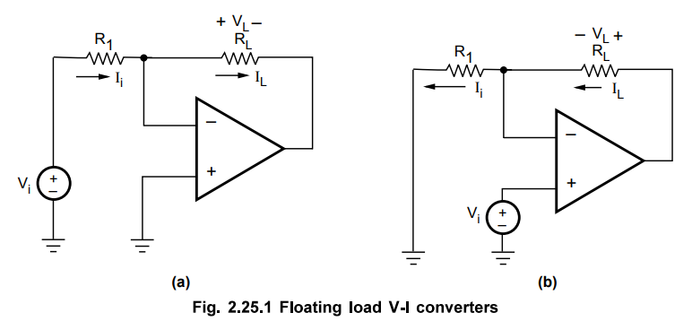
As
input current of op-amp is zero.
IL
= Ii – Vi / R1 … (2.25.1)
IL
∝ Vi
… (2.25.2)
Key Point Thus the load
current is always proportional to the input voltage and circuit works as
voltage to current converter.
If
the load is a capacitor, it will charge or discharge at a constant rate. Hence
such converter circuits are used to generate the sawtooth or triangular
waveforms. The proportionality constant is generally 1/R1 hence this
circuit is also called transconductance amplifier It is also called a Voltage
Controlled Current Source (VCCS).
The
expression IL = Vi/R1 holds regardless of the
type of the load. It can be linear (e.g., a resistive) or non-linear (e.g., a
light emitting diode), or it can have time-dependent characteristics (e.g., a
capacitor). No matter what the load is, the op-amp will draw the current Ii
whose magnitude depends only on Vi and R.
2. Voltage to Current Converter with Grounded Load
When
one of end of the load is grounded, it is no longer possible to place the load
within feedback loop of the op-amp. Fig. 2.25.2 shows a voltage to current
converter in which one end of load resistor RL is grounded. It is
also known as 'Howland Current Converter' from the name of its inventor.
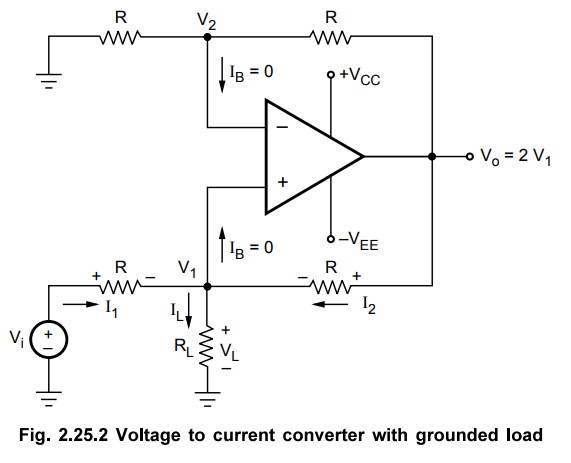
The
analysis of the circuit is accomplished by first determining the voltage Vi at
the non-inverting input terminal and then establishing the relationship between
V1 and the load current.
Applying
KCL at node V1 we get, I1 +I2 = IL
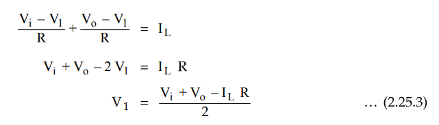
The
gain of op-amp in non-inverting mode is given as A = 1 + Rf/R1
For this circuit it is 1 + R/R = 2. Hence, output voltage can be written as,

From
the above equation we can say that the load current depends on the input
voltage Vi and resistor R.
3. Applications of V-I Converter
a.
Low Voltage D.C. Voltmeter
The
V-I converter circuit with floating load can be modified as a low voltage d.c.
voltmeter circuit. The resistance RL is to be replaced by D'Arsonval
meter movement. This is shown in the Fig. 2.25.3.

For
accurate readings it is necessary to make the nulling of op-amp. This is done
by offset voltage compensating network. Let Rm be the meter
resistance. The effective Thevenin's equivalent of compensating network is 10 Ω.
Hence when switch S is in position 1, the effective R1 is 1 kΩ + 10Ω
≈ 1 kΩ.

So
current of 1 mA i.e. input of 1 V will result full scale deflection, if meter
has full scale deflection current of 1 mA.
When
switch is in position 2 then Ri = 5 kΩ. Thus for full scale deflection,

Thus
5 V are required to cause full scale deflection. Thus range of voltmeter
increases by 5. Similarly at positions 3 and 4, ranges of X10 and X13 are also
obtained.
Remember
that for ±15 V supply, maximum input voltage range is ±14 V hence with ±15 V
supply, maximum range possible is X13.
It
is important to note that meter resistance Rm does not affect the
value of Io. Thus meter can be calibrated properly to measure d.c. voltages.
b.
Low Voltage A.C. Voltmeter
To
measure a.c. voltages, the full wave bridge rectifier is used and D'Arsonval
meter movement is used. The combination of meter and rectifier is used in the
feedback loop of a.c. voltmeter. The circuit is shown in the Fig. 2.25.4.
The
alternating current Io is converted to d.c. During positive half cycle of Vin
the diodes D3 and D4 conduct while for negative half cycle of Vin the diodes D1
and D2 conduct. The direction of current through meter is always same for both
the half cycles of Vin. Thus meter gives the average (d.c.) value of the
rectified current. If it is necessary to calibrate the meter interms of r.m.s.
values of input voltage then the factor 1.11 must be considered which relates
r.m.s. and average values for purely sinusoidal waveforms. The range can be
extended using the selector switch S and various resistances as shown in the
Fig. 2.25.4. At position 2, X2 can be obtained. At position 3, X5 range can be
obtained. At positition 4, X10 range can be obtained. It must be noted that due
to low slew rate of 741 op-amp, the input a.c. voltage frequency should not be
greater than 4 kHz. Similarly PIV ratings of the diodes must be large than the
saturation voltages of op-amp.

c.
Diode
Tester and Match Finder
Another
application of V-I converter is a diode tester and diode match finder. The resistance RL is replaced by a
diode as shown in the Fig. 2.25.5.
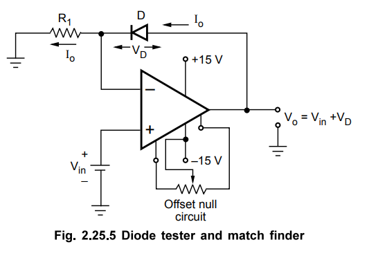
The
current Io is set by Vin and resistance R1.
Io
= Vin / R1
So
as long as Vin and R1 are constants, the current Io
is also constant. The drop across diode can be directly measured by the
voltmeter or the output voltage will be Vo = Vin + VD
From the value of VD, the diode can be judged for its performance.
Note that to avoid error in the output voltage, op-amp should be initially
nulled using offset null circuit.
Similarly
replacing diodes one after the other, the perfectly matched diodes can be found
out. R1 can be selected according to Vin and testing
current Io required in the circuit.
The
V-I converter circuit can also be used to test zener diode. The zener diode is
connected in reverse biased condition in the feedback path as shown in the Fig.
2.25.6.

The
current Io is set by Vin and R1.
If
this current is more than knee current of the zener then voltage across zener
is VZ for which it is rated. Similarly matched zeners also can be
obtained using same circuit.
The
same circuit can be used for LED testing and match finding by replacing the
feedback path by LED under test. The brightness of LEDS can be tested by
setting specific current using Vin and R1.
In
all the applications, as 741 is used it is necessary to note that short circuit
current rating of op-amp i.e. 25 mA should not be exceeded by the current Io.
Example
2.25.1 For a V-I convertor shown in Fig. 2.25.7, Vin
- 5 V, R - 10 k Ω, V1 =1V, find the load
current and output voltage Vo. Assume the op-amp is initially
nulled.
Dec.-14,
Marks 6
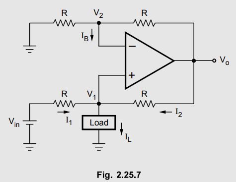
Solution: Assume IB = 0 A.

The
gain of the op-amp circuit in non inverting mode is A = 1 + R/R = 2.
Vo
= 2V1 = 2 × 1 = 2 V
Using
in equation (1), 5 + 2 – 2 / 10×103
= IL
i.e.
IL = 0.5 mA
Review Questions
1. Draw and explain
the circuit of a voltage to current converter if the load is 1) Floating 2)
Grounded.
May-04, 10, 12,
Dec.-06, 08, 10, Marks 8
2. With the help of
circuit diagram explain the operation of V to I converter and its applications.
Dec.-06, 07,11,
May-13,15, 17, Marks 8
Linear Integrated Circuits: Unit II: Characteristics of Op-amp : Tag: : Working Principle, Circuit Diagram, Applications, Solved Example Problems | Operational amplifier - Op-amp Voltage to Current Converter
Related Topics
Related Subjects

Linear Integrated Circuits
EE3402 Lic Operational Amplifiers 4th Semester EEE Dept | 2021 Regulation | 4th Semester EEE Dept 2021 Regulation