Electron Devices and Circuits: Unit III: (b) MOSFET Amplifier
Operation of MOSFET amplifier
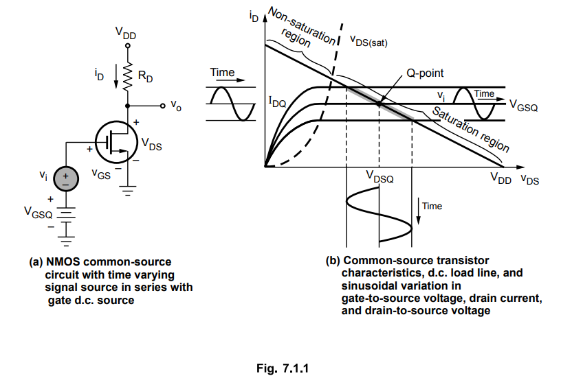
• Fig. 7.1.1 shows n-channel, enhancement mode MOSFET common-source circuit with a time-varying (a.c.) voltage source in series with the d.c. source. We assume the time-varying input signal is sinusoidal.
Introduction
•
Fig. 7.1.1 shows n-channel, enhancement mode MOSFET common-source circuit with
a time-varying (a.c.) voltage source in series with the d.c. source. We assume
the time-varying input signal is sinusoidal.
•
Fig. 7.1.1 shows the MOSFET characteristics, d.c. load line, and Q-point, where
the d.c. load line and Q-point are functions of vGS, VDD RD and the MOSFET
parameters.
•
For the output voltage to be a linear function of the input voltage, the MOSFET
is biased in the saturation region.
•
The Fig. 7.1.1 (b) shows sinusoidal variations in the gate-to-source voltage,
drain current and drain-to-source voltage, as a result of the sinusoidal source
v .
•
The total gate-to-source voltage is the sum of VGSQ and vi.
•
As Vi increases, the instantaneous value of VGS increases, and the bias point
moves up the load line. A larger value of VGS means a larger drain current and
a smaller value of VDS .
Review Question
1. Explain the operation of CS EMOSFET amplifier with the help
of dc load line.
Electron Devices and Circuits: Unit III: (b) MOSFET Amplifier : Tag: : - Operation of MOSFET amplifier
Related Topics
Related Subjects

Electron Devices and Circuits
EC3301 3rd Semester EEE Dept | 2021 Regulation | 3rd Semester EEE Dept 2021 Regulation