Microprocessors and Microcontrollers: Unit IV: (c) Programmable Interval Timer (PIT/C) 8253/8254
Operational Description
Programmable Interval Timer (PIT/C) 8253/8254
The complete functional definition of the 8253/54 is programmed by the system software. Once programmed, the 8253/54 is ready to perform whatever timing tasks it is assigned to accomplish.
Operational Description
AU
: Dec.-11, 16
The
complete functional definition of the 8253/54 is programmed by the system
software. Once programmed, the 8253/54 is ready to perform whatever timing
tasks it is assigned to accomplish.
Programming
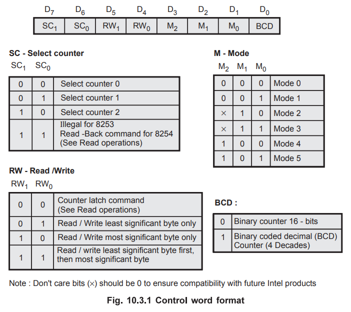
the 8253/54 : Each counter of the 8253/54 is
individually programmed by writing a control word into the control word
register (A0 A1 = 11). The Fig. 10.3.1 shows the control
word format. Bits SC1 and SC0 select the counter, bits RW1
and RW0 select the read, write or latch command, bits M2,
M1 and M0 select the mode of operation and bit BCD decides
whether it is a BCD counter or binary counter.
WRITE
Operation :
1.
Write a control word into control register.
2.
Load the low-order byte of a count in the counter register.
3.
Load the high-order byte of count in the counter register.
READ
Operation : In some applications, especially in
event counters, it is necessary to read the value of the count in process. This
can be done by three possible methods :
1.
Simple Read : It involves reading a count after
inhibiting the counter by controlling the gate input or the clock input of the
selected counter, and two I/O read operations are performed by the CPU. The
first I/O operation reads the low-order byte, and the second I/O operation
reads the high order byte.
2.
Counter Latch Command : In the second method, an
appropriate control word is written into the control register to latch a count
in the output latch, and two I/O read operations are performed by the CPU. The
first I/O operation reads the low-order byte, and the second 1/O operation
reads the high order byte.
3.
Read-Back Command (Available only for 8254) : The
third method uses the Read-Back command. This command allows the user to check
the count value, programmed mode, and current status of the OUT pin and Null
count flag of the selected counter(s). Fig. 10.3.2 shows the format of the
control word register for Read-Back command.
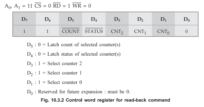
D5
: 0 = Latch count of selected counters)
D4
: 0 = Latch status of selected counters)
D3
: 1 = Select counter 2
D2
: 1 = Select counter 1
D1
: 1 = Select counter 0
D0
: Reserved for future expansion : must be 0.
Fig.
10.3.2 Control word register for read-back command
The
Read-Back command may be used to latch multiple counter output latches by
setting the  bit D5 = 0 and selecting the desired
counter(s). Each counter's latch count in held until it is read (or the counter
is reprogrammed). That counter is automatically unlatched when read.
bit D5 = 0 and selecting the desired
counter(s). Each counter's latch count in held until it is read (or the counter
is reprogrammed). That counter is automatically unlatched when read.
Other
Features of Read - Back Command (Available only for 8254) :
The
Read-Back command may also be used to latch status information of selected
counter(s) by setting STATUS bit D4 = 0. The contents of the counter must be
latched before reading. The status of a counter is then accessed by a read from
that counter. The Fig. 10.3.3 shows the counter status format.
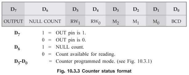
Bit
D5 – D0 contains the counter's programmed mode exactly as
written in the last mode control word. Bit D7 contains the current
status of the output pin. In 8254, it is not possible to read count from the
counter, if the count is not loaded into the Counting Element (CE). The Bit D6
indicates whether the counting element has count or not. If D6 = 0,
counting element has count otherwise null count.
Interleaved
Read and Write : Another feature of the 8254 is that
reads and writes of the same counter may be interleaved. For example, if the
counter is programmed for the two byte counts, the following sequence is valid.
1.
Read least significant byte
2.
Write new least significant byte.
3.
Read most significant byte.
4.
Write new most significant byte.
Review Questions
1. Draw the control
word of 8253 timer/counter and explain. AU : Dec.-11, Marks 8
2. Explain the
working of 8254 timer with a neat block diagram and its command word format. AU : Dec.-16, Marks
8
Microprocessors and Microcontrollers: Unit IV: (c) Programmable Interval Timer (PIT/C) 8253/8254 : Tag: : Programmable Interval Timer (PIT/C) 8253/8254 - Operational Description