Digital Logic Circuits: Unit IV: (c) Introduction to Programmable Logic Devices
PAL (Programmable Array Logic)
Concept, Architecture, Example Problems
• The commercial PAL devices has more gates than the one shown in Fig. 9.4.1. A typical PAL integrated circuit may have eight inputs, eight outputs, and eight sections, each consisting of an eight wide AND-OR array.
PAL (Programmable Array Logic)
AU
: Dec.-04, 05, 15, 17, May-05, 12
•
We have seen that PLA is a device with a programmable AND array and
programmable OR array. However, PAL programmable array logic is a programmable
logic device with a fixed OR array and a programmable AND array. Because only
AND gates are programmable, the PAL is easier to program, but is not as
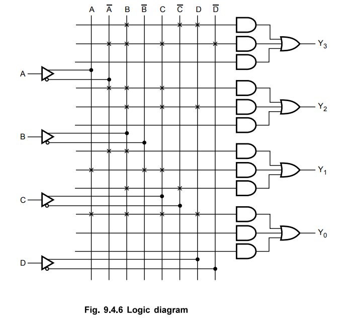
flexible as the PLA. Fig. 9.4.1 shows the array logic of a typical PAL. It has
four inputs and four outputs. Each input has buffer and an inverter gate. It is
important to note that two gates are shown with one composite graphic symbol
with normal and complement outputs. There are four sections. Each section has
three programmable AND gates and one fixed OR gate. The output of section 1 is
connected to a buffer-inverter gate and then fed back into the inputs of the
AND gates, through fuses. This allows the logic designer to feed an output
function back as an input variable to create a new function. Such PALs are
referred to as Programmable I/O PALs.
•
The commercial PAL devices has more gates than the one shown in Fig. 9.4.1. A
typical PAL integrated circuit may have eight inputs, eight outputs, and eight
sections, each consisting of an eight wide AND-OR array.

1. Implementation of combinational Logic Circuit using PAL
•
Let us see the implementation of a combinational circuit using PAL with the
help of examples.
Examples
for Understanding
Ex.
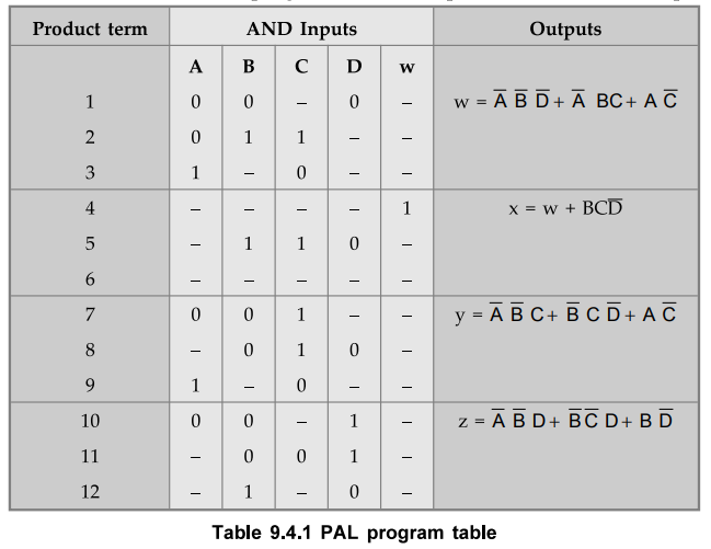
9.4.1 Implement the following Boolean functions using PAL.
w
(A, B, C,D) = ∑ m (0, 2, 6, 7, 8, 9, 12, 13),
x
( A,B,C,D) = ∑ m (0, 2, 6, 7, 8, 9, 12, 13, 14)
y
( A,B,C,D) = ∑ m (2, 3, 8, 9, 10, 12,13),
z
( A,B,C,D) = ∑ m (1, 3, 4, 6, 9, 12, 14)
Sol.
:
Step
1 :
Simplify the four functions

Note
that function x has four product terms. Three of them are equal to w. Therefore
we can write
Step
2 :
Implementation
In
the last section we have seen the PLA program table. The program table for PAL
is similar to PLA program table. Table 9.4.1 shows PAL program table with
product terms, AND inputs and outputs.

Ex.
9.4.2 Design BCD to Excess-3 converter using PAL.
Sol.
: Step 1 : Derive the truth table of BCD to Excess-3 converter

Step
2 :
Simplify the Boolean functions for Excess-3 code outputs.
Step
3 :
Implementation

Ex.
9.4.3 Generate the following Boolean functions with a PAL with 4 inputs and 4
outputs.
Sol.
:
Step
1 :
Simplify the Boolean functions

Step
2 :
Implementation
Ex.
9.4.4 Show how to program the fusible links to get a 4 bit gray code from the
binary inputs using PLA and PAL and compare the design requirements with PROM.
Sol.
: Implementation using PROM

Table
3.21.4 shows the truth table for binary to gray code converter. There are four
binary inputs, i.e. 24 = 16 minterms. These minterms can be implemented using
fixed AND array of 16 AND gates of the PROM. Since there is four bit Gray code
output, we need four OR gates. Thus we need 16x4 PROM. We know that in PROM
OR-Array is programmable and hence there are 16x4 = 64 fusible links. These 64
fusible links are programmed according to gray code column of Table 3.21.4.
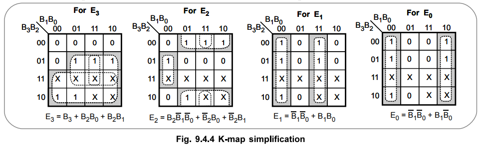
Referring
example 3.21.4 we have simplified expressions for 4-bit binary to gray code
conversion are as follows :
Implementation
using PLA
For
PLA both AND-array and OR-Array have fusible links. From simplified Boolean
expression we have seven product terms and these can be implemented using seven
eight-input AND gates. We need four OR-gates for four-bit gray code output.
Thus we need 4 × 7 × 4 PLA in place of 16 × 4 PROM. There are (8 + 4) × 7 = 84
fusible links compared to 64 fusible links in PROM. Fig. 9.4.7 shows
implementation of 4-bit binary to gray code converter using 4 × 7 × 4 PLA.

Implementation
using PAL
For PAL, AND array is programmable and has fusible links. From simplified Boolean expression we have seven product terms and these can be implemented using seven eight input AND gates. We need four OR-gates for four-bit gray code output. Thus we need 7x4 PAL in place of 16x4 PROM. There are 7 x 8 = 56 fusible links compared to 64 fusible links in PROM. Fig. 9.4.8 shows implementation of 4-bit binary to gray code converter using PAL.

Example
for Practice
Ex.
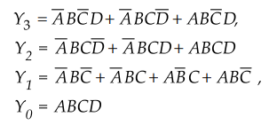
9.4.5 A combinational logic circuit is defined by the following function.
f1(a,b,c)
∑ (0,1,67), f2 (a,b,c) = ∑ (2,
3,5,7).
Implement
the circuit with a PAL having three inputs, three product terms and two
AU
: May-05, 12, Marks 10
Review Questions
1. What is PAL ?
2. Whether PAL is same as PLA ? Explain.
AU : May-05, Dec.-05, Marks 2
3. Write a note on PAL.
Digital Logic Circuits: Unit IV: (c) Introduction to Programmable Logic Devices : Tag: : Concept, Architecture, Example Problems - PAL (Programmable Array Logic)
Related Topics
Related Subjects

Digital Logic Circuits
EE3302 3rd Semester EEE Dept | 2021 Regulation | 3rd Semester EEE Dept 2021 Regulation