Electric Circuit Analysis: Unit I: b. Basic circuits analysis
Parallel Combination of Resistors
with Circuit Diagram, Equation, Solved Example Problems, Applications, Disadvantage
Worked examples on series resistive circuits with Circuit Diagram, Equation, Solved Example Problems, Applications, Disadvantage
COMBINATION OF RESISTORS
In a practical case we may have many resistors. We have to connect them for getting desired resistance. The resistors can be connected in the following three fashions.
(a) Series combination
(b) Parallel combination
(c) Series - parallel combination
Parallel Combination
If
one end of all the resistors is joined to a common point and the other ends are
joined to another common point, the combination is said to be parallel
combination between two common points.
A
voltage source is connected between the common points. Hence the currents flow
through different resistors. The voltage across each resistor will be the same
as the supply voltage. So, the current through each element can be found by
applying ohm's law for each resistor separately. The current is inversely
proportional to the resistance.
Let
R1, R2 and R3 be the three resistors connected
between the two common terminals A and B. Let V be the voltage supplied between
A and B. Refer the fig.1.10
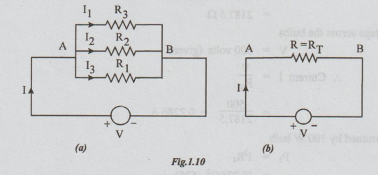
I1,
I2 and I3 are the currents through R1, R2
and R3 respectively.
By
ohm's law: I1=V/R1
I2=
V/R2
I3
= V/R3
I
= IT = the total current = source current
Let
R be the equivalent resistance of the combination
Refer
figure 1.10(b). I = V / R
But
I = I1 + I2 +13... (i)
Substituting
the above expressions for the currents in equation (i), we get
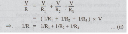
Hence,
in the case of parallel combination the reciprocal of the equivalent resistance
is equal to the sum of reciprocals of individual resistances.
Multiplying
both sides of equation (ii) by V2, we get
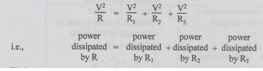
We
know that reciprocal of resistance is called conductance.
i.e.,
conductance = 1/ Resistance
or G = 1 / R
The above equation (ii) can be written as
G
= G1 + G2 + G3
Important points in Parallel combination of resistors
1.
Voltage is same across all elements. In other words, if the voltage is same the
combination is parallel combination.
2.
The current through the various resistors are different. The current through
resistor is inversely proportional to its resistance.
3.
The total resistance of a parallel circuit is always lesser than the smallest
of the resistances.
4.
Powers are additive.
5.
The source current is the sum of the branch currents.
6.
Conductance's are additive.
Advantages of parallel circuits
1.
The electrical appliances of different power ratings may be rated for the same
voltage. For example, in a house tube lights, bulbs, fridge, fans, motor are
all rated for 230 volts. But their power ratings are different. In such cases
if they are all connected in parallel the performance of others will not be
affected.
2.
In case a break (open) occurs in any of the branch circuits it, will not affect
the other branch circuits. It is advantage only.
Applications of parallel circuits
1.
All electrical appliances are connected in parallel. Each one of them can be
controlled individually with the help of a separate switch.
2.
Electrical wiring in cinema Halls, auditoriums, house wiring etc.
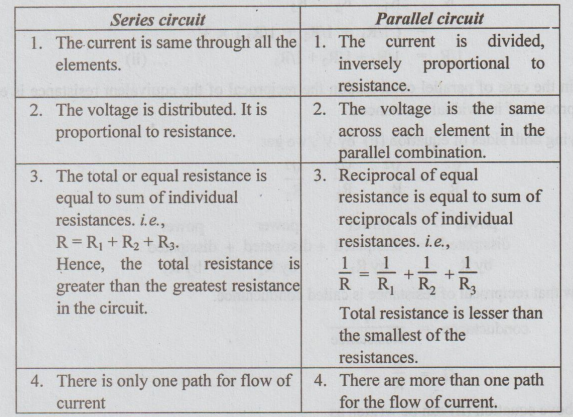
Comparison of series and parallel circuits
WORKED EXAMPLES ON D.C. PARALLEL CIRCUITS
Example 1 In the circuit shown in fig, calculate
(i) the current in other resistors.
(ii) the value of unknown resistance 'X'.
(iii) the equivalent resistance across A - B.
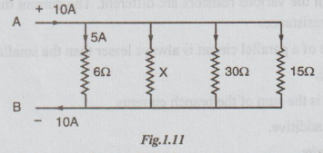
Solution: As all the resistors are in parallel, the voltage across each one is same. Given that current through 6Ω = 5A.
Voltage across 6 Ω = 5 × 6 = 30 volts [By Ohm's law]
Again, by Ohm's law, current through 30 Ω,
I30 = 30/30 = 1A
and current I15 = 30/15 = 2A
Given I6 = 5A
But I = I6 + Ix + I30 + I15 [By KCL]
⇒ 10 = 5 + Ix + 1 + 2
Ix = 2A
By applying ohm's law to x ohms resistor,
x = 30/Ix = 30/2 = 15 Ω
Let the equivalent resistance across AB = R
1/R = 1/6 + 1/x + 1/30 + 1/15
= 1/6 + 1/15 + 1/30 + 1/15
= 5 + 2 + 1 + 1/30 = 1/3
R = 30 Ω
Ans: (i)Ix = 2A
I30= 1A
I15 =2A
(ii) X =15Ω
(iii)R=RAB = 3 Ω
Note: We can calculate R by applying ohm's law to the circuit shown above.
R = voltage / current = 30/10= 3 Ω
Example 2 Two resistors are connected in parallel and a voltage of 200 volts is applied to the terminals. The total current taken is 25A and the power dissipated in one of the resistors is 1500 W. What is the resistance of each element?
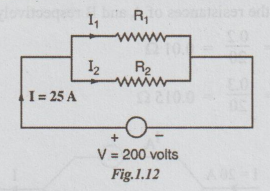
Solution:
V = 200 volts
I = 25A
Power dissipated by one resistor
(say) R1 = P1 = 1500 watts
But P1 =V2/R1
⇒R1 = V2/P1
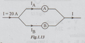
Substituting the values, we get
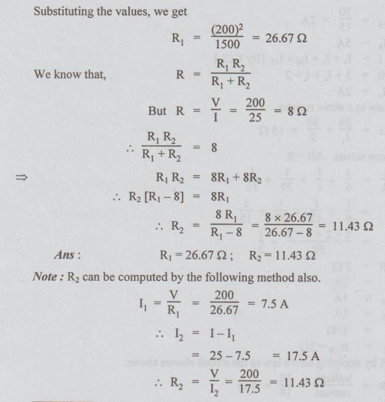
Example 3 A current of 20A flows through two ammeters A and B joined in series. Across A, the p.d is 0.2 V and across B it is 0.3 V. Find how the same current will be divided between A and B when they are joined in parallel.
Solution: Let RA and RB be the resistances of A and B respectively.
By ohm's law,
RA = 0.2/20 = 0.01 Ω
RB = 0.3/20 = 0.015 Ω
By division of current formula
IA = IRB /RA+RB = 20 × 0.015/0.01 + 0.015= 12A
But, by KCL, IA + IB = 1
⇒ IB = I - IA
= 20-12=8A
Ans:IA= 12A; IB = 8A
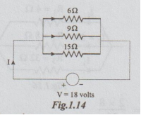
Example 4 Three resistors of 6 Ω, 9 Ω and 15 Ω are connected in parallel to a 180 V supply. Calculate (a) the current in each branch of the network. (b) the supply current (c) the total resistance of the network.
Solution:
By ohm's law applied to each resistor, we get
I6 = 18/6=3A
I9 =18/9 = 2A
I15=18/15 =1.2A
Supply Current = Source Current
By KCL, ISource = Source Current
ISource = I6 + I9 + I15
= 3+2+1.2
= 6.2 A
By Ohm's law,
Total resistance R = V/Isource
=18 / 6.2 Ω = 2.9 Ω
Answers: (i) I6 = 3A
I9 = 2A
I15 = 1.2 A
(ii) Isource = 6.2 A
(iii )R = 2.9 Ω
Example 5 A parallel network consists of three resistors of 4 Ω, 8 Ω and 32 Ω If the current in the 8 resistor is 2A, what are the currents in the other resistors?
Solution:
Since the resistors are connected in parallel, voltage across them is the same.
i.e., I2R2 = I1R1 = I3R3 = V
I1 = I2 R2/ R1 = 2 × 8/4 = 4A
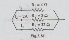
I3 = I2R2/R3 = 2 × 8/32
= 0.5A
Ans: I1 = 4A; I3 = 0.5 A
Example 6 Calculate the current supplied by the battery in the given circuit of the Fig1.17 (a).
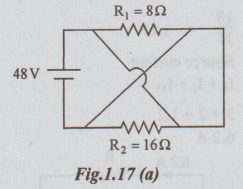
Solution: For easy understanding the given circuit can be re-drawn as shown in Fig.1.17 (b). There is no change in the connections.
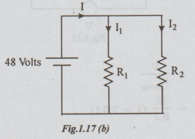
R1 and R2 are in parallel across the voltage of 48 volts.
The total resistance R = R1 R2 / R1 + R2
= 8 × 16 / 8 + 16 = 16/3 Ω
Equivalent circuit is
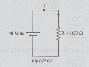
Current from battery by Ohm's law,
I = V / R = 48 /16/3 = 9A
Note: From Fig.(b), by applying ohm's law to R1 and R2, we get I1 and I2
I1 = V/ R1 = 48/8 = 6A
and I2 = R2 = 48/16 = 3A
I = I1 + I2
= 6+3 = 9A
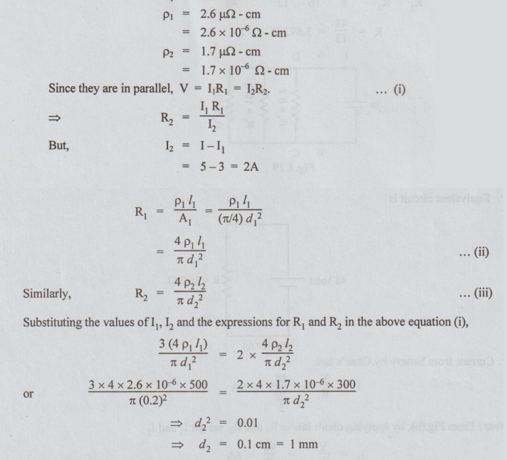
Example 7 An aluminium wire of 5 m length and 2 mm diameter is connected in parallel with a copper wire of 3m long. Total current is 5A and that in aluminium is 3A. Find the diameter of copper wire. The specific resistances of aluminium and copper are 2.6 μΩ⇒cm and 1.7 μΩcm respectively.
Solution: Data: Use suffix 1 for aluminium and suffix 2 for copper.
l1 = 5m = 500cm
d1 = 2mm = 0.2cm
l2 = 3m = 300cm
I = 5A
I1 = 3A
Example 8 Calculate the total resistance and battery current in the given circuit.
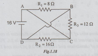
Solution: The given circuit is re-drawn as below. A and D are connected by wire of zero resistance. Hence they can be shown together similarly B and C can be shown as same terminal. Let R be the total resistance between A and B.
Then, R = R1 || R2 || R3
1/R =1/R1+1/R2+1/R3=1/8 +1/16 + 1/12 = 6+3+4/48
R = 48/13= 3.692Ω
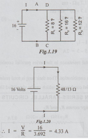
I = V/R = 16/3.692 = 4.33A
Ans: (i) R = 3.692 Ω (ii) I = 4.33 A
Note: We can find the currents I1, I2 and I3 by ohm's law. Then I and R can be calculated as shown below.
I1 = V/R1 = 16/8 = 2A
I2 = V/R2 = 16/16 = 1A
I3 = V/R3 = 16/12 = 1.33 A
By KCL, I = I1 + I2 + I3
= 2 + 1 + 1.33 = 4.33 A Ans.
And by Ohm's law, R = V/I = 16/4.333 = 3.692 Ω Ans.
Electric Circuit Analysis: Unit I: b. Basic circuits analysis : Tag: : with Circuit Diagram, Equation, Solved Example Problems, Applications, Disadvantage - Parallel Combination of Resistors
Related Topics
Related Subjects

Electric Circuit Analysis
EE3251 2nd Semester 2021 Regulation | 2nd Semester EEE Dept 2021 Regulation