Electrical Machines: Unit IV: Single Phase Transformer
Parallel Operation of Transformers with Unequal Voltage Ratios
Single Phase Transformer
• The voltage ratios of the two transformers are not equal. The parallel operation under this case is still possible. But as seen previously there would be a circulating current under no load condition.
Parallel
Operation of Transformers with Unequal Voltage Ratios
AU: Dec.-05, 06
•
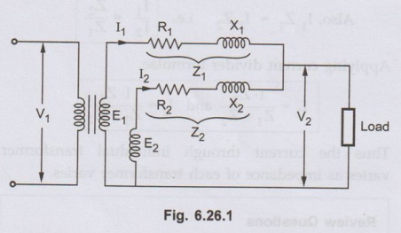
Now we will consider the case of two transformers working in parallel and
having unequal voltage ratio. This is shown in the Fig. 6.26.1.
•
The voltage ratios of the two transformers are not equal. The parallel
operation under this case is still possible. But as seen previously there would
be a circulating current under no load condition.
•
Let us consider voltage ratio of transformer 1 is slightly more than 2. So that
induced e..m.f. E1 is greater than E2. Thus the resultant
terminal voltage will be E1 - E2 which will cause a
circulating current under no load condition.
Ic =E1-E2 / Z1+Z2
From
the circuit diagram we have,

Key Point:
This circulating current IC adds to I1, but subtracts
from I2. Hence transformer 1 gets overloaded. The transformers will
not share the load according to their ratings.
•
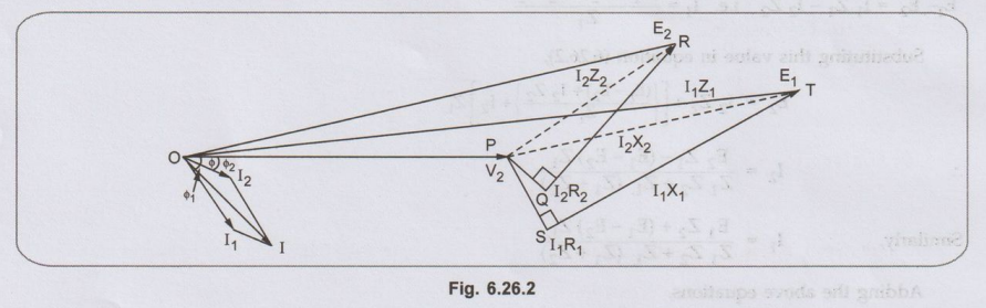
The phasor diagram is shown in the Fig. 6.26.2.
•
The two transformers will operate at different power factors ϕ1 and ϕ2
are the power factor angles of these two transformers whereas is the combined
p.f. angle.
•
Here EA and EB have the same phase but there may be some
phase difference between the two due to some difference of internal connection
as for the connection in parallel of a Star/Star and a Star/Delta 3 phase
transformers.
Key Point:
While solving the problems on parallel operation of transformers it is
convenient to work with numerical values of impedances instead of percentage
values.
Ex. 6.26.1
Two transformers A and B are connected in
parallel to a load of (2 + j1.5)Ω. Their impedances in secondary terms are ZA
(0.15+j0.5) Ω and ZB = (0.1+j0.6) Ω.
Their no load terminal voltages are EA = 207 ∠0° V and EB = 205 40° volts. Find the
power output and power factor of each transformer.
Sol.
Two transformers A and B are supplying a load of impedance given by,

Ex. 6.26.2 Two
transformers each of 800 kVA are connected in parallel. One has a resistance
and reactance of 1% and 4 % respectively and the other has resistance and
reactance of 1.5 % and 6 % respectively. Calculate the load shared by each
transformer and corresponding power factor when the total load shared is 100
kVA at 0.8 power factor lagging.
Sol.:
kVA of transformer 1 = 800 and kVA
of transformer 2 = 800

Ex. 6.26.3 Two single phase transformers, one
of 100 kVA and the other of 60 kVA are connected in parallel to the same bus
bars on the primary side their no load secondary voltage being 1000 V and 900 V
respectively. Their resistances are 2.0 and 2.5 percent respectively and their
reactances are 8 and 6 percent respectively. Calculate no load circulating
current in the secondaries.
Sol. :
Transformer 1 :

Review Questions
1. Deduce expressions
for the load shared by the two transformers with unequal voltage ratios. AU: Dec.-05, 06,
Marks 12
2. Two 100 kW single
phase transformers are connected in parallel both on the primary and secondary.
One transformer has an ohmic drop of 0.5 % at full load and an inductive drop
of 8 % at full load current. The other has an ohmic drop of 0.75 % and
inductive drop of 2 %. Show how will they share a load of 180 kW at 0.9 power
factor. [Ans.:
kW1, 57.9, kW2 = 121.5]
3. A load of 200 kW at 0.85 power factor
lagging is to be shared by two transformers A and B having the same rating and
same transformation ratio. For transformer A the full load resistive drop is 1
% and reactance drop 5 % of the nominal terminal voltage for transformer B the
corresponding values are 2 % and 6 %. Calculate the load kVA supplied by each
transformer. [Ans.: KVAA =
131; kVAB = 105]
4. A load of 450 kVA at 0.8 power factor
lagging is to be shared by two three phase transformers A and B of equal
ratings. If the equivalent delta Tow impedances as referred to secondary are
(1.5 + j 5) Ω for A and (1.5 + j 4.5) Ω for B, calculate the load supplied by
each transformer. [Ans.: QA=214.25 ∠-37.77° KVA, QB
= 235.7865 ∠-36.03°KVA]
5. A 500 kVA
transformer with 0.01 pu resistance and 0.05 pu reactance is connected in
parallel with a 250 kVA transformer with 0.015 pu resistance and 0.04 pu
reactance. The secondary voltage of each transformer is 400 V on no load. Find
how they share a load of 750 kVA at power factor 0.8 lagging.
[Ans. : 471.16 ∠- 40.31° kVA, 280.90 ∠- 31.06° KVA]
6. Two 250 kVA
transformers suppling a network are connected in parallel on both primary and
secondary sides. Their voltage ratios are the same. The resistance drops are
1.5 % and 0.9 % and the reactance drops are 3.33 % and 4 % respectively.
Calculate the kVA loading on each transformer and its power factor when the
total load on the balls transformers is 500 kVA and at 0.707 lagging p.f. [Ans.: 265.8 kVA,
0.7709 (lag), 236.8 kVA, 0.6276 (lag]
Electrical Machines: Unit IV: Single Phase Transformer : Tag: : Single Phase Transformer - Parallel Operation of Transformers with Unequal Voltage Ratios
Related Topics
Related Subjects

Electrical Machines I
EE3303 EM 1 3rd Semester EEE Dept | 2021 Regulation | 3rd Semester EEE Dept 2021 Regulation