Electrical Machines: Unit IV: Single Phase Transformer
Parallel Operation of Two Ideal abrupse Single Phase Transformers
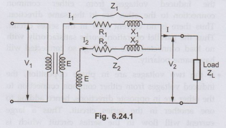
• Now we will consider ideal case of two transformers having the same voltage ratio and their voltage triangles are equal in size and shape. The circuit shown in the Fig. 6.24.1 consists of two transformers in parallel.
Parallel Operation
of Two Ideal abrupse Transformers
AU: May-15
•
Now we will consider ideal case of two transformers having the same voltage
ratio and their voltage triangles are equal in size and shape. The circuit
shown in the Fig. 6.24.1 consists of two transformers in parallel.
•
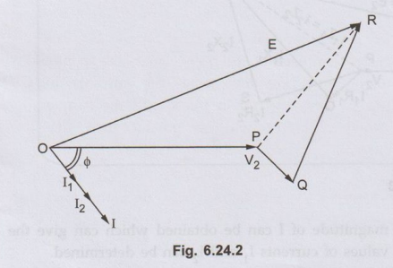
The corresponding phasor diagram is shown in the Fig. 6.24.2
•
As seen from the Fig. 6.24.2 the impedance voltage triangles of both the
transformers is same. I1 and I⁄2 are the currents flowing
through transformers A and B which are in parallel. These currents are in phase
with the load current and are inversely proportional to the respective
impedances.
Applying
KCL, I = I1 + I2
Secondary
voltage,
V2
= E - I1 Z1 = E – I2 Z2
Also
I1Z1 = I2
Z2 i.e. I1 / I2 = Z2 /Z1
Applying
current divider formulae,
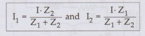
Thus
the current through individual transformer varies as impedance of each
transformer varies.
Review Questions
1. Explain the
parallel operation of two ideal dere transformers.
2. Explain the effect
of impedance variation on load sharing between transformers in parallel. AU May-15, Marks 4
Electrical Machines: Unit IV: Single Phase Transformer : Tag: : - Parallel Operation of Two Ideal abrupse Single Phase Transformers
Related Topics
Related Subjects

Electrical Machines I
EE3303 EM 1 3rd Semester EEE Dept | 2021 Regulation | 3rd Semester EEE Dept 2021 Regulation