Electric Circuit Analysis: Unit V: Resonance and coupled circuits
Parallel Resonance Circuit
In parallel circuits, it is easier to analyse if the admittance is calculated. At resonance, the power factor being unity, reactive part of Z and reactive part of Y must be zero.
PARALLEL RESONANCE CIRCUIT
In
parallel circuits, it is easier to analyse if the admittance is calculated. At
resonance, the power factor being unity, reactive part of Z and reactive part
of Y must be zero. Equating the reactive part of Y (admittance) to zero, we can
get the expression for resonant frequency. At resonance the admittance is
minimum and hence impedance is maximum. In other words, current is minimum.
1. Case (a): Resonance in Parallel RLC Circuit (Ideal Circuit)
Consider
the parallel RLC circuit shown in the fig. 5.8.

For
this ideal case the expression for resonant frequency seems to be same as that
of series resonant frequency.
At
resonance, the parallel RLC circuit behaves simply as resistance, the parallel
LC combination known as a tank circuit behaves as an open circuit. But it does
not mean that there is no current in the inductor and capacitor. The current
actually circulates around the loop formed by the inductor and capacitor.
The quality factor Q = Ic (or) IL / I at resonance = R / ω0L CR ... (2)
2. Case (b): Resonance in a Parallel Practical Circuit
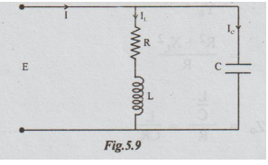
The
admittance of the circuit = Y = Yc + YL
=
1 / Zc + 1 / ZL
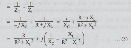
At
resonance, the reactive part of Y must be zero.

At
resonance, the admittance is denoted by Y0.
From
equation (3),
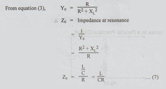
Z0
is the dynamic impedance of the circuit. It is independent of frequency. The
impedance is a pure resistance. Lower the resistance of the coil, higher the
value of Z0. Hence, the value of impedance at resonance is maximum
and the resultant current is minimum.
A
parallel resonant circuit is also called a rejector circuit since, the current
at resonance is minimum. In other words, a tank circuit rejects the current at
resonance. The current at resonance
=
I0 = E/Z0 = ECR/L … (8)
This
current is minimum current.
Effects
of parallel resonance
For
the circuit shown, at resonance,
(a)
Impedance = L / CR. It is purely resistive.
(b)
As L/C is very large, at resonance the impedance Zr is very high.
(c)
The circuit current is very small.
As
a parallel resonant circuit draws a very small current and power from the
mains, it is often regarded as rejector circuit.
Current
Magnification
At
resonance, in a parallel circuit, the branch current may be many times greater
than the supply current. By means of a parallel resonance circuit, the current
taken from supply can be greatly magnified. Hence, this type of resonance is
called current resonance.
Current
magnification = Ic / I = ω0L / R = Q factor of the circuit
Thus
Q factor is a measure of current magnification in a parallel resonant circuit.
3. Case (c): Parallel Resonance
(Two branch circuit, one branch consisting of
R-L and another of R - C.)
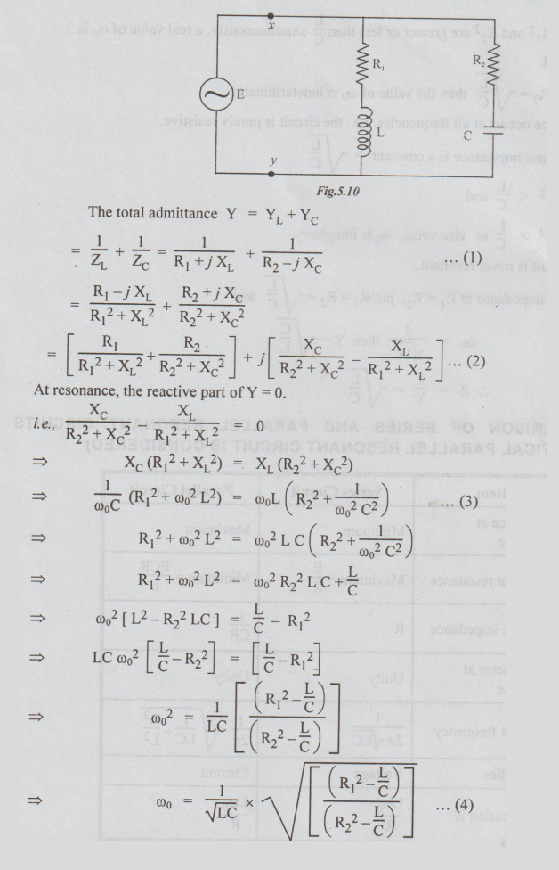
Note:
From equation (4), the following observations can be made
(i)
If R1 = R2, ω0 = 1/√LC
(ii)
If both R12 and R22 are greater or
less than L/C simultaneously, a real value of is ω0 obtained.
(iii)
If R1 R = R2 = √L/C then the value of ω0 is
indeterminate.
i.e.,
resonance occurs at all frequencies. i.e., the circuit is purely resistive.
In
this case impedance is a constant = √L/C
(iv)
If R12 < L/C and
R22
> L/C or vice versa, ω0 is
imaginary.
i.e.,
the circuit is never resonant.
(v)
To find impedance at R1 = R2, put R1 = R2
= √L/C and
ω0
= 1/√L/C then Y = -√C/L
Z
= 1/Y = √L/C
COMPARISON OF SERIES AND PARALLEL RESONANT CIRCUITS
(PRACTICAL PARALLEL RESONANT CIRCUIT IS CONSIDERED)

Electric Circuit Analysis: Unit V: Resonance and coupled circuits : Tag: : - Parallel Resonance Circuit
Related Topics
Related Subjects

Electric Circuit Analysis
EE3251 2nd Semester 2021 Regulation | 2nd Semester EEE Dept 2021 Regulation