Electrical Machines: Unit IV: Single Phase Transformer
Parts of Transformer
The various parts of transformer are,
Parts of
Transformer
The
various parts of transformer are,
1. Core: It
is made up of high grade silicon steel laminations. Its function is to carry
the flux, providing low reluctance to it. Generally 'L' es shaped or 'I' shaped
laminations are used as shown in the Fig. 6.3.1.

2. Limb : It
is vertical portion of the core and its function is to carry the windings.
3. Yoke :
The top and bottom horizontal portion of the core is called yoke. Its function
is to carry the flux produced by one winding to reach to the other winding and
provide the low reluctance path to the flux.
4. Windings:
The coils used are wound on the limbs and are insulated from each other. The
function of the windings is to carry the current and produce the flux necessary
for the functioning of the transformer.
5. Conservator:
The oil in the transformer expands when temperature inside the transformer
increases due to heat while it contracts when the temperature decreases. The
function of the conservator is to take up the expansion and contraction of the
oil without allowing it to come in contact with the ambient air.
6. Breather :
Smaller transformers are not fully filled with oil and some space remains
between oil level and tank. The tank is connected to atmosphere by vent pipe.
When oil expands air goes out while when oil contracts the air is taken in. The
breather is a device which extracts the moisture from the air when the air is
taken in and does not allow oil to come in contact with the moisture. The
breathers contain the silica gel crystals which immediately absorb the atmospheric
moisture.
7. Explosion vent:
It is a bent pipe fitted on the main tank which acts as a relief valve. It uses
nonmetallic diaphragm which bursts when pressure inside the transformer becomes
excessive which releases the pressure and protects the transformer.
8. Buchholz relay :
It is a safety gas operated relay connected to transformer. When the fault gets
developed inside the transformer, the gases are released. The Buchholz relay is
operated with these gases and trips the circuit breaker to n protect the
device.
1. Construction Features
•
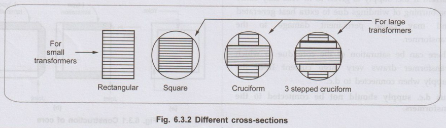
The cross-section of the limb depends on
the type of coil to be used either circular or rectangular. The different
cross-sections of limbs, practically used are shown in the Fig. 6.3.2.
• To avoid the high reluctance at the joint, the alternate layers are stacked differently to eliminate the joints. This is called staggering. The butt joints are staggered in alternate layers. It is shown in the Fig. 6.3.3.

The
advantages of staggering in transformer are,
1.
It avoids continuous air gap.
2.
The reluctance of magnetic circuit gets reduced.
3.
The continuous air gap reduces the mechanical strength of the core. The
staggering helps to increase the mechanical strength of the core.
2. Types of Windings
•
The coils used are wound on the limbs and are insulated from each other. In the
basic transformer shown in the Fig. 6.2.2, the two windings wound are shown on
two different limbs i.e. primary on one limb while secondary on other limb. But
due to leakage flux increases which affects the transformer performance badly.
Similarly it is necessary that the windings should be very close to each other
to have high mutual inductance. To achieve this, the two windings are split
into number of coils and are wound adjacent to each other on the same limb. A
very common arrangement is cylindrical concentric coils as shown in the Fig.
6.3.4 (a)

•
Such cylindrical coils are used in the core type transformer. These coils are
mechanically strong. These are wound in the helical layers. The different
layers are insulated from each other by paper, cloth or mica. The low voltage
winding is placed near the core from ease of insulating it from the core. The
high voltage is placed after it.
•
The other type of coils which is very commonly used for the shell type of
transformer is sandwich coils. Each high voltage portion lies between the two
low voltage portion sandwiching the high voltage portion. Such subdivision of
windings into small portions reduces the leakage flux. Higher the degree of
subdivision, smaller is the reactance. The sandwich coil is shown in the Fig.
6.3.4 (b). The top and bottom coils are low voltage coils. All the portions are
insulated from each other by paper.

•
The transformers are generally kept in
tightly fitted sheet metal tanks. The tanks are constructed of specified high
quality steel plate cut, formed and welded into the rigid structures. All the
joints are painted with a solution of light blue chalk which turns dark in the
presence of oil, disclosing even the minutest leaks. The tanks are filled with
the special insulating oil. The entire transformer assembly is immersed in the
oil. The oil serves two functions:
i)
Keeps the coils cool by circulation and
ii)
Provides the transformers an additional insulation.
•
The oil should be absolutely free from alkalies, sulphur and specially from
moisture. Presence of very small moisture lowers the dielectric strength of
oil, affecting its performance badly. Hence the tanks are sealed air tight to
avoid the contact of oil with atmospheric air and moisture.
Review Questions
1. What are the main
parts of transformer? State the function of each part.
2. State the advantages
of staggering.
3. Write a note on
types of windings used in transformers.
Electrical Machines: Unit IV: Single Phase Transformer : Tag: : - Parts of Transformer
Related Topics
Related Subjects

Electrical Machines I
EE3303 EM 1 3rd Semester EEE Dept | 2021 Regulation | 3rd Semester EEE Dept 2021 Regulation