Transmission and Distribution: Unit II: (a) Modelling and Performance of Transmission Lines
Performance Analysis of Short Transmission Lines
In the analysis of short transmission lines, the capacitive effects are small and neglected. The resistance and inductance of the line are only taken into consideration.
Performance Analysis of
Short Transmission Lines
The equivalent circuit for a short
transmission line is represented in the Fig. 2.5.1. In the analysis of short
transmission lines, the capacitive effects are small and neglected. The
resistance and inductance of the line are only taken into consideration. These
parameters are taken to be lumped instead of distributed for the analysis. The
circuit then simplifies to a simple a.c. series circuit as shown in the Fig.
2.5.1.
AU: May-17, Dec.-17
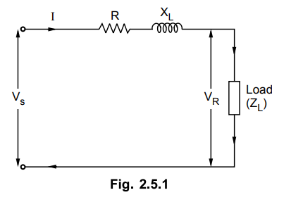
Let
I = Load Current
R = Resistance of the loop i.e.
resistance of both conductors
XL = Inductive loop reactance
VR = Receiving end voltage, cos
ϕR = Receiving end power factor
VS = Sending end voltage, cos
ϕS Sending end power factor
ZL = Load impedance
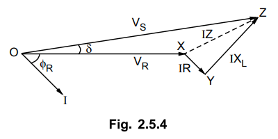
The corresponding phasor diagram is
shown in the Fig. 2.5.2 for lagging load power factor.
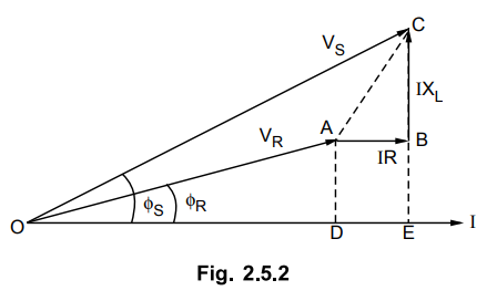
From the right angled triangle OEC we
have,
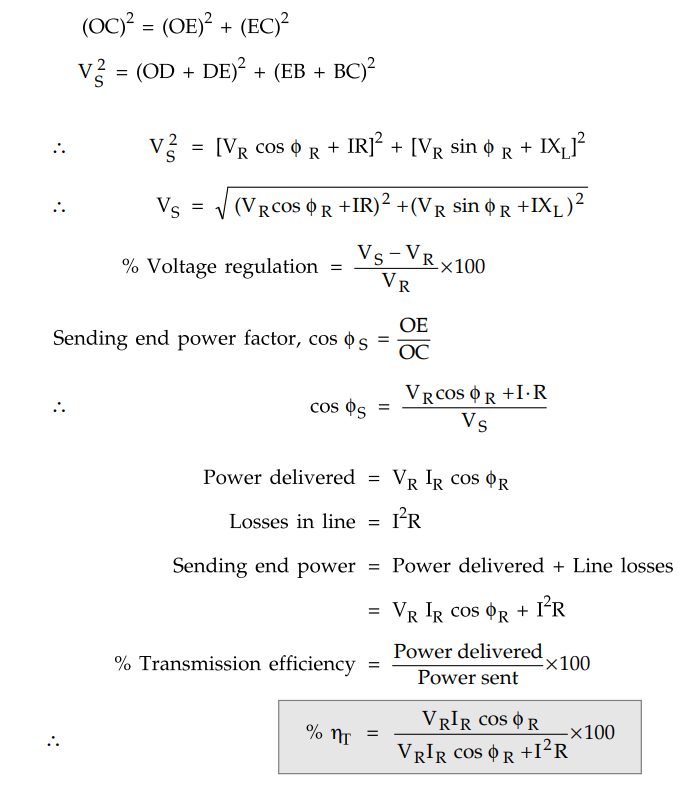
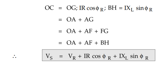
The approximate expression for sending end voltage Vs can be obtained as follows. Draw the perpendicular from B and C on OA produced which is shown in the Fig. 2.5.3.
By making this adjustment we
can see that OC = OG.
Use of complex notation :
Many a times it is convinient to make
the analysis of line in complex notation. The phasor diagram is shown in the
Fig. 2.5.4.
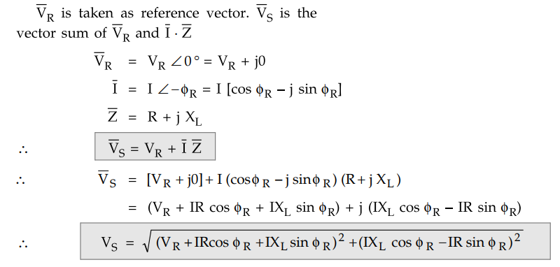
It can be seen that the second term in
the above equation is very small and can be neglected without losing much
accuracy. Therefore approximate expression for VS is
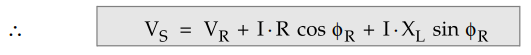
The important point to be noted that the
approximate formula for Vs gives more accurate results for lagging power
factors. But appriciable error is seen in case of leading power factors. Hence this expression for Vg is
to be applied to the loads having lagging power factors.
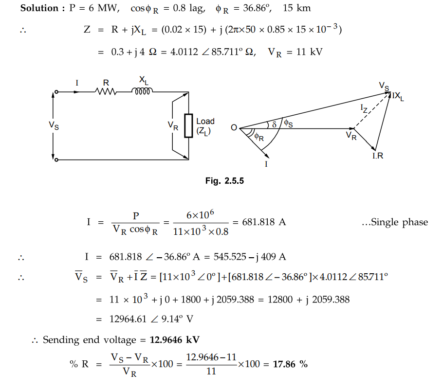
Example 2.5.1
A single phase 50 Hz generator supplies an inductive load of 6 MW at 0.8 pf
lagging by means of an overhead line 15 km long. The line resistance and
inductance are 0.02 ohm/km and 0.85 mH/km. The voltage at the receiving end is
11 kV. Determine the sending end voltage and voltage regulation.
Solution :
Review Question
1. Deduce an expression for voltage regulation and
transmission efficiency of a single phase short transmission line, giving the
vector diagram.
Transmission and Distribution: Unit II: (a) Modelling and Performance of Transmission Lines : Tag: : - Performance Analysis of Short Transmission Lines
Related Topics
Related Subjects

Transmission and Distribution
EE3401 TD 4th Semester EEE Dept | 2021 Regulation | 4th Semester EEE Dept 2021 Regulation