Electrical Machines II: UNIT I: b. Armature Reaction and Regulation of Alternators
Phasor Diagram of a Loaded Alternator
The above voltage equation is to be realised using phasor diagrams for various load power factor conditions.
Phasor Diagram of a Loaded Alternator
The above voltage equation is to be realised using phasor diagrams for various load power factor conditions. For drawing the phasor diagram consider all per phase values and remember following steps.
Steps
to draw the phasor diagram :
1.
Choose current Ia as a reference phasor.
2.
Now if load power factor is cos ty , it indicates that angle between Vph
and Ia is ty as Vph is the voltage available to the load.
So
show the phasor Vph m such a way that angle between Vph
and Ia is ϕ . For lagging ϕ’, Ia should lag Vph
and for leading ϕ', Ia should lead Vph- For unity power
factor load ϕ is zero, so Vph and Ia are in phase.
3.
Now the drop IaRa is a resistive drop and hence will
always be in phase with Ia. So phasor Ia Ra
direction will be always same as Ia, i.e. parallel to Ia.
But as it is to be added to Vph, Ia Ra phasor must be drawn from the tip of the Vph
phasor drawn.
4.
The drop IaXs is drop across purely inductive reactance. In pure inductance,
current lags voltage by 90°. So ’I aXs' phasor direction
will be always such that Ia will lag IaXs phasor by 90°.
But this phasor is to be drawn from the tip of the IaRa
phasor to complete phasor addition of Vph,IaRa
and IaXs
5.
Joining the starting point to the terminating point, we get the phasor Eph.
Whatever may be the load power factor, Ia Ra is a
resistive drop, will be in phase with Ia while IaXs is
purely inductive drop and hence will be perpendicular to Ia in such
a way that Ia will lag IaXs by 90°. This is
shown in the Fig. 2.9.1.

By
using the above steps, the phasor diagrams conditions can be drawn.
1. Lagging Power Factor Load
The
power factor of the load is cos ϕ lagging so Ia lags Vph
by angle ϕ. By using steps discussed above, phasor diagram can be drawn as
shown in the Fig. 2.9.2.
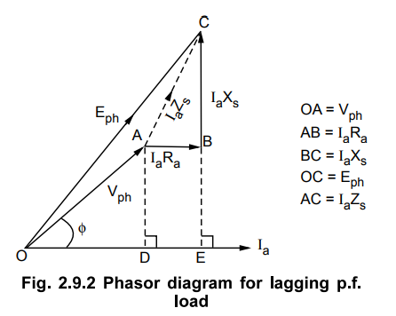
To
derive the relationship between Eph and Vph, the
perpendiculars are drawn on the current phasor from points A and B. These
intersect current phasor at points D and E respectively.
Now,
OD = Vph cos ϕ
AD
= BE = Vph sin ϕ
DE
= IaRa
Consider
∆ OCE, for which we can write,
(OC)2
= (OE) 2 + (EC) 2
(Eph)
2 = (OD + DE) 2 + (EB + BC) 2
(Eph)
2 = (Vph cos ϕ + IaRa)2 + (Vph
sinϕ + IaXs)2
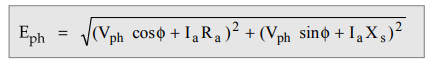
From
this equation, the value of induced e.m.f. can be calculated.
2. Leading Power Factor Load
The
power factor of the load is cos ϕ leading. So Ia leads Vph
by an angle ϕ . By using steps discussed, the phasor diagram can be drawn as
shown in the Fig. 2.9.3.
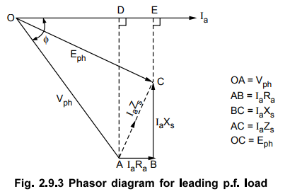
To
derive the relation between Eph and Vph, the
perpendiculars are drawn on current phasor from points A and B. These intersect
current phasor at points D and E respectively.
From
∆
OAD, OD = Vph cos ϕ
AD
= BE = Vph sin ϕ
DE
= IaRa
Consider
∆ OCE, for which we can write,
(OC)2
= (OE) 2 + (EC) 2
(Eph
) 2 = (OD + DE) 2 + (BE - BC) 2
(Eph)
2 = (Vph cos ϕ + IaRa) 2 + (Vph sin ϕ IaXs) 2
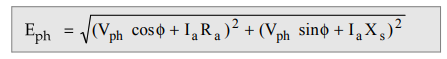
It
can be observed that the sign of the IaXs is negative as
against its positive sign for lagging p.f. load. This is because X5
consists of Xar. i.e. armature reaction reactance. Armature reaction
is demagnetising for lagging while magnetising for leading power factor loads.
So sign of IaXs is opposite for lagging and leading p.f
conditions.
3. Unity Power Factor Load
The
power factor of the load is unity i.e. cos ϕ = 1. So ϕ = 0, which means Vph
is in phase with Ia. So phasor diagram can be drawn as shown in the
Fig. 2.9.4.
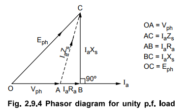
Consider
∆ OBC, for which we can write,
(OC)2
= (OB)2 + (BC)2
(Eph)
2 - (OA + AB) 2 + (BC) 2
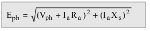
(Eph)
2 = (Vph + IaRa) 2 + (IaXs)
2
As
cos ϕ = 1, so sin ϕ = 0 hence does not appear in the equation.
Note : The phasor diagrams
can be drawn by considering voltage Vph as a reference phasor. But to derive
the relationship, current phasor selected as a reference makes the derivation
much more simplified. Hence current is selected as a reference phasor.
It
is clear from the phasor diagram that Vph is less than Eph
for lagging and unity p.f. conditions due to demagnetising and cross
magnetising effects of armature reaction. While Vph is more than Eph
for leading p.f. condition due to the magnetising effect of armature reaction.
Thus
in general for any power factor condition,
(Eph)2
= (Vph cosIaRa)2 + (Vph sinIaXa)2
+
Sign for lagging p.f. loads
-
Sign for leading p.f. loads
and Vph = Per phase rated terminal
voltage
Ia
= Per phase full load armature current
From
this discussion, we can now define the voltage regulation of an alternator
The
angle between Eph and Vph is called load angle and
denoted as δ.
Review Questions
1. Draw the vector diagram of an alternator supplying lagging,
leading and unity power factor load and hence derive an expression for the no
load e.m.f. in terms of terminal voltage, load current, armature resistance and
synchronous reactance.
2. Draw the vector diagrams of loaded alternator for lagging,
leading and unity power factor conditions and explain them.
Electrical Machines II: UNIT I: b. Armature Reaction and Regulation of Alternators : Tag: Engineering Electrical Machines - II : - Phasor Diagram of a Loaded Alternator
Related Topics
Related Subjects

Electrical Machines II
EE3405 Machine 2 EM 2 4th Semester EEE Dept | 2021 Regulation | 4th Semester EEE Dept 2021 Regulation