Electrical Machines II: UNIT III: a. Three Phase Induction Motor
Phasor Diagram of Induction Motor
The phasor diagram of loaded induction motor is similar to the loaded transformer.
Phasor Diagram of Induction Motor
The
phasor diagram of loaded induction motor is similar to the loaded transformer.
The only difference is the secondary of induction motor is rotating and short
circuited while transformer secondary is stationary and connected to load. The
load on induction motor is mechanical while load on transformer is electrical.
Still by finding electrical equivalent of mechanical load on the motor, the
phasor diagram of induction motor can be developed.
Let ϕ = Magnetic flux links with both primary
and secondary
There
is self induced e.m.f. Ej in the stator while a mutually induced e.m.f. E2r in
the rotor.
Let R1 = Stator resistance per phase
X1
= Stator reactance per phase
The
stator voltage per phase V1 has to counter balance self induced
e.m.f. E1 and has to supply voltage drops I1 R1 and
I1 X1 So on stator side we can write,

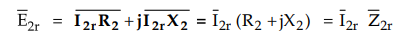
The
rotor induced e.m.f. in the running condition has to supply the drop across
impedance as rotor is short circuited.
The
value of E2r depends on the ratio of rotor turns to stator turns.
The
rotor current in the running condition is hr which lags E2r by rotor
p.f. angle ϕ2r
The
reflected rotor current I2r on stator side is the effect of load and
is given by,
I2r
- K I2r
The
induction motor draws no load current Io which is phasor sum of Ic
and Im. The total stator current I1 drawn from supply is,
The
ϕ1 is angle between V1 and I1 and cos ϕ1
gives the power factor of the inductor motor.
Thus
using all above relations the phasor diagram of induction motor on load can be
obtained.
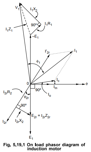
The
steps to draw phasor diagram are,
1.
Take ϕ as reference phasor.
2.
The induced voltage E1 lags ϕ by 90°.
3.
Show – E1by reversing voltage phasor E1.
4.
The phasor E2r is in phase with E1. So show I2r
lagging E2r i.e. E1 direction by ϕ2r
5.
Show I2r R2 in phase with I2r and I2r X2r leading the resistive drop by
90°, to get exact location of E2r
6.
Reverse I2r to get I2r.
7.
Im is in phase with ϕ while Ic is at 90° leading with .
Add Im and Ic to get Io.
8.
Add Io and I2r to get I1.
9.
From tip of – E1 phasor, add I1 R1 in phase
with I1 and I1 X1 at 90° leading to I1
to get V1 phasor.
10.
Angle between V1 and I1 is ϕ1.
The
phasor diagram is shown in the Fig. 5.19.1
Review Question
1. Draw and explain the phasor of diagram of a three phase
induction motor.
Electrical Machines II: UNIT III: a. Three Phase Induction Motor : Tag: Engineering Electrical Machines - II : - Phasor Diagram of Induction Motor
Related Topics
Related Subjects

Electrical Machines II
EE3405 Machine 2 EM 2 4th Semester EEE Dept | 2021 Regulation | 4th Semester EEE Dept 2021 Regulation