Electrical Machines: Unit IV: Single Phase Transformer
Phasor Diagrams for Transformer on Load
Single Phase Transformer
• Consider a transformer supplying the load as shown in the Fig. 6.12.1.
Phasor
Diagrams for Transformer on Load
AU: Dec.-02,17, May-06,10,14
•
Consider a transformer supplying the load as shown in the Fig. 6.12.1.

The
various transformer parameters are,
R1
= Primary winding resistance,
X1
= Primary leakage reactance
R2
= Secondary winding resistance,
X2
= Secondary leakage reactance
Z1
= Load impedance, I1 = Primary current
I2
= Secondary current = IL = Load current
whereI0
= No load current
I
'2
= Load component of current decided by the load
=
K I2 where K is transformation ratio
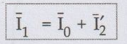
The
primary voltage V1 has now three components,
1.
- E1, the induced e.m.f. which opposes V1
2.
I1 R1, the drop across the resistance, in phase with I1
3.
I1X1, the drop across the reactance, leading I1
by 90°
•
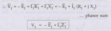
The secondary induced e.m.f. E2 has also three components,
1.
V2, the terminal voltage across the load
2.
I2 R2', the drop across the resistance, in phase with I2
3.
I2 X2', the drop across the reactance, leading I2
by 90°
•
The phasor diagram for the transformer on load depends on the nature of the
load power factor. Let us consider the various cases of of the load power factor.
1. Unity Power Factor Load, cos ϕ2 = 1
•
As load power factor is unity, the voltage V2 and I2 are
in phase. Steps to draw the phasor diagram are,
1.
Consider flux ϕ as reference
2.
E1 lags ϕ by 90°. Reverse E1 to get - E1.
3.
E1 and E2 are in phase.
4.
Assume V2 in a particular direction.
5.
I2 is in phase with V2.
6.
Add I2 R2 and I2 X2 to V2
to get E2.
7.
Reverse I2 to get I'2.
8.
Add I0 and I'2 to get I1.
9.
Add I1 R1 and I1 X1 to - E1
to get V1.
Angle between V1 and I1 is ϕ1 and cos ϕ1 is primary power factor. Remember that I1X1, leads I1 direction by 90° and I2 X2 leads I2 by 90° as current through inductance lags voltage across inductance by 90°. The phasor diagram is shown in the Fig. 6.12.2.

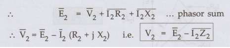
2. Lagging Power Factor Load, cos ϕ2
As
load power factor is lagging cos ϕ2, the current I2 lags
V2 by angle ϕ2. So only change in drawing the phasor diagram
is to draw I2 lagging V2 by ϕ2 in step 5
discussed earlier. Accordingly directions of I2R2, I2X2,
I'2, I1,I1R1, and I1 X1,
will change. Remember that whatever may be the power factor of load, I2X2
leads I2, by 90° and IX1 leads I1 by 90°. The complete phasor
diagram is shown in the Fig. 6.12.3.
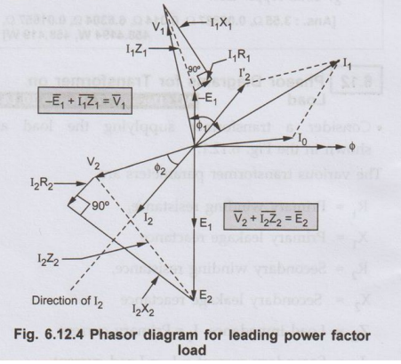
3. Leading Power Factor Load, cos ϕ2
• As load power factor is leading, the current
I2 leads V2 by angle ϕ2. So the change is to
draw I2, leading V2 by angle ϕ2. All other
steps remain same as before. The complete phasor diagram is shown in the Fig.
6.12.4.
Review Question
1. Draw a phasor
diagram to represent conditions in a single phase transformer supplying load
at: 1) Unity p.f. 2) Lagging p.f. and 3) Leading p.f. AU: Nov.-02, Dec.-17,
May-06, 10, 14, Marks 8
Electrical Machines: Unit IV: Single Phase Transformer : Tag: : Single Phase Transformer - Phasor Diagrams for Transformer on Load
Related Topics
Related Subjects

Electrical Machines I
EE3303 EM 1 3rd Semester EEE Dept | 2021 Regulation | 3rd Semester EEE Dept 2021 Regulation