Electric Circuit Analysis: Unit I: b. Basic circuits analysis
Phasor representation of sinusoidally varying alternating quantities
Basic circuits analysis
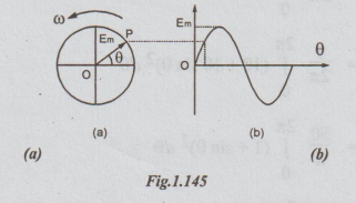
Consider a phasor OP = Em Em is the maximum value of alternating voltage, which varies sinusoidally. Let this phasor rotate in the anti-clockwise direction at a speed of a radians/sec.
PHASOR REPRESENTATION OF SINUSOIDALLY VARYINGALTERNATING
QUANTITIES
Consider
a phasor OP = Em Em is the maximum value of alternating
voltage, which varies sinusoidally. Let this phasor rotate in the
anti-clockwise direction at a speed of a radians/sec.
The
phasor and the voltage wave forms are shown in the figures 1.145 (a) and 1.145
(b) respectively.
Any
alternating sinusoidal quantity can be represented by a rotating phasor, if it
satisfies the following conditions.
(a)
The magnitude of rotating phasor should be equal to the maximum value of the
quantity.
(b)
The rotating phasor should start initially at zero and then move in positive
direction (anti- clockwise direction).
(c)
The speed of the rotating phasor should be in such a way that during its one
revolution the alternating quantity completes one cycle.
Note:
(i)
Generally the effective values (RMS values) are used to represent the phasors.
(ii)
For sinusoidal alternating quantities, effective value = RMS value = 0.707 ×
maximum value.
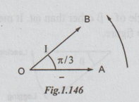
Let
us consider the following two sinusoidal equations.
1.
e = 200 sin ωt
2.
i = 10 sin (ωt + π/3)
It
is required to show the above equations as phasors. The following steps are
used for this. Only RMS values are considered.
Step
1:
Find RMS value for each.
Thus,
Irms = 0.707 × 10 = 7.07A
and
Erms = 0.707 × 200 = 141.4V
Step
2:
Take quantity having the angle as oot along positive x-axis. Here, voltage has
got the angle ωt (no plus or no minus angle other than ot). Select a voltage
scale and draw a line OA to represent 141.4V.
Step
3: The
rms value of current 7.07A. Take a suitable current scale and draw a line OB,
at an angle π/3, in anti-clockwise direction, from voltage OA. OB represents
current phasor.
Thus
the voltage phasor and the current phasor are shown for the given sinusoidally
varying voltage and currents.
Note:
1.
If both equations are sinusoidally varying with the same angle ot, both phases
are shown along positive x-axis. Such quantities attain their maximum (or
minimum) values simultaneously and are said to be in phase.
Example,
e = Em sin ωt
I
= Im sin ωt
Phasor
representation
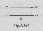
OA
represents E and OB represents I.
2.
The alternating quantities which vary sinusoidally, but having different
angles, are said to be out of phase or there is said to be existence of phase
difference.
The
quantity having angle only ωt is taken as reference. The other quantity is
compared with the reference quantity. The quantity with ωt + some angle is said
to be leading the other one.
Let
e = Em sin ωt
i
= Im sin (ωt + α)
Here,
angle of i is a more than that of e. So we, say that current leads the voltage
by angle a. The leading quantity is shown making an angle a with E, in the
anticlockwise direction. It is shown below.
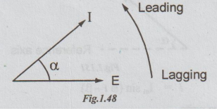
An
alternating quantity with negative angle (other than wt) is said to be lagging.
Consider
the following two equations
e
= Em sin ωt
i
= Im sin (ωt -β)
The
current phasor has got an angle of - ẞ other than ot. It means that current
lags behind the voltage by B. The phasors are as shown in the figure.
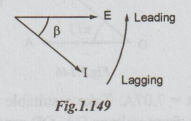
In
the above phasor diagram, an arrow is given in anti-clockwise direction. It
shows the direction of the rotation of the phasors. Leading quantity is shown
on arrow side and lagging quantity on tail side.
Electric Circuit Analysis: Unit I: b. Basic circuits analysis : Tag: : Basic circuits analysis - Phasor representation of sinusoidally varying alternating quantities
Related Topics
Related Subjects

Electric Circuit Analysis
EE3251 2nd Semester 2021 Regulation | 2nd Semester EEE Dept 2021 Regulation