Electrical Machines: Unit IV: Single Phase Transformer
Polarity Test
Single Phase Transformer
When the primary winding of a transformer is excited with suitable rated voltage then e.m.f. gets induced in both the windings. The polarities of these e.m.f.s depend on how the windings are wound on the core.
Polarity
Test
•
When the primary winding of a transformer is excited with suitable rated
voltage then e.m.f. gets induced in both the windings. The polarities of these
e.m.f.s depend on how the windings are wound on the core. It is usual practice
to determine which ends of the two windings acquire simultaneously positive or
negative polarity. This polarity determination is carried out by conducting the
polarity test on a transformer.
•
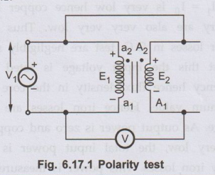
Consider a transformer shown in the Fig. 6.17.1. Usually the ends of the L.V.
winding are lebelled with small letters as a1,a2 while
the ends of the H.V. windings are lebelled with capital letters as A1,
A2
•
In determining the relative polarity of the two windings of a transformer using
polarity test, the two windings are connected in series across a voltmeter. The
voltmeter is connected across a1 - A1.
•
One of the windings is excited by suitable voltage source. So a1 – a2,
is excited by voltage V1. Let E1 and E2, are
the induced e.m.f.s
Key Point:
If the voltmeter reads E1 ~ E2, thus voltmeter reading is
less than V1, then the polarities are called subtractive in nature.
•
The net voltage acting around the local circuit consisting the voltmeter is E1
~ E2. In such case the ends a2, A2 are
simultaneously positive or negative. This is indicated by dots, as shown in the
Fig. 6.17.1.
Key Point:
But if the windings are wound in such a way that the voltmeter reads E1
+ E2 polarities are said to be additive.
•
In such case the voltmeter reading is more than V1. This confirms
that if a2, is positive, terminal A2 is negative and
vice-versa. In such case, the polarity markings of one of the windings must be
interchanged.
Key Point: In
practice the transformer windings are wound in such a way that the relative
polarities are subtractive which in indicated by dots, as per the dot convention.
Review Question
1. What is polarity
test? Why it is required to be performed? How it is performed ? Draw the vigg
suitable circuit diagram.
Electrical Machines: Unit IV: Single Phase Transformer : Tag: : Single Phase Transformer - Polarity Test
Electrical Machines: Unit IV: Single Phase Transformer
Under Subject

Electrical Machines I
EE3303 EM 1 3rd Semester EEE Dept | 2021 Regulation | 3rd Semester EEE Dept 2021 Regulation
Related Subjects

Probability and complex function
MA3303 3rd Semester EEE Dept | 2021 Regulation | 3rd Semester EEE Dept 2021 Regulation

Electromagnetic Theory
EE3301 3rd Semester EEE Dept | 2021 Regulation | 3rd Semester EEE Dept 2021 Regulation

Digital Logic Circuits
EE3302 3rd Semester EEE Dept | 2021 Regulation | 3rd Semester EEE Dept 2021 Regulation

Electron Devices and Circuits
EC3301 3rd Semester EEE Dept | 2021 Regulation | 3rd Semester EEE Dept 2021 Regulation
Electrical Machines I
EE3303 EM 1 3rd Semester EEE Dept | 2021 Regulation | 3rd Semester EEE Dept 2021 Regulation

C Programming and Data Structures
CS3353 3rd Semester EEE, ECE Dept | 2021 Regulation | 3rd Semester EEE Dept 2021 Regulation