Electrical Machines II: UNIT I: b. Armature Reaction and Regulation of Alternators
Potier's Triangle Method or Zero Power Factor (ZPF) Method
Synchronous Generator or Alternators
This method is also called Potier method.
Potier's Triangle Method or Zero Power Factor (ZPF) Method
AU
: April-96, 2000, Dec.-06, 08, May-09, 12, 13, 16, 17,18
This
method is also called Potier method. In the operation of any alternator, the
armature resistance drop IRa and armature leakage reactance drop IXL are
actually e.m.f. quantities while the armature reaction is basically m.m.f.
quantity. In the synchronous impedance all the quantities are treated as e.m.f.
quantities as against this in M.M.F. method all are treated as m.m.f.
quantities. Hence in both the methods, we are away from reality.
Key Point : This method is
based on the separation of armature leakage reactance and armature reaction
effects. The armature leakage reactance XL is called Potier
reactance in this method, hence method is also called Potier reactance method.
To
determine armature leakage reactance and armature reaction m.m.f. separately,
two tests are performed on the given alternator. The two tests are,
1.
Open circuit test 2. Zero power factor test
1. Open Circuit Test
The experimental setup to perform this test is
shown in the Fig. 2.15.1.

The steps to perform open circuit test are,
1.
The switch S is kept open.
2.
The alternator is driven by its prime mover at its synchronous speed and same
is maintained constant throughout the test.
3.
The excitation is varied with the help of potential divider, from zero upto
rated value in definite number of steps. The open circuit e.m.f. is measured
with the help of voltmeter. The readings are tabulated.
4.
A graph of If and (VOC)ph i.e. field current
and open circuit voltage per phase is plotted to some scale. This is open
circuit characteristics.
2. Zero Power Factor Test
To
conduct zero power factor test, the switch S is kept closed. Due to this, a
purely inductive load gets connected to an alternator through an ammeter. A
purely inductive load has power factor of cos 90° i.e. zero lagging hence the
test is called zero power factor test.
The
machine speed is maintained constant at its synchronous value. The load current
delivered by an alternator to purely inductive load is maintained constant at
its rated full load value by varying excitation and by adjusting variable
inductance of the inductive load. Note that, due to purely inductive load, an
alternator will always operate at zero p.f. lagging.
Key Point : In this test,
there is no need to obtain number of points to obtain the curve. Only two
points are enough to construct a curve called zero power factor saturation
curve.
This
is the graph of terminal voltage against excitation when delivering full load
zero power factor current.
One
point for this curve is zero terminal voltage (short circuit condition) and the
field current required to deliver full load short circuit armature current.
While other point is the field current required to obtain rated terminal
voltage while delivering rated full load armature current. With the help of
these two points the zero p.f. saturation curve can be obtained as,
1.
Plot open circuit characteristics on graph paper as shown in the Fig. 2.15.2.

2.
Plot the excitation corresponding to zero terminal voltage i.e. short circuit
full load zero p.f. armature current. This point is shown as A in the Fig.
2.15.2 which is on the x-axis. Another point is the rated voltage when
alternator is delivering full load current at zero p.f. lagging. This point is
P as shown in the Fig. 2.15.2.
3.
Draw the tangent to O.C.C. through origin which is line OB as shown dotted in
the Fig. 2.15.2. This is called air line.
4.
Draw the horizontal line PQ parallel and equal to OA.
5.
From point Q draw the line parallel to the air line which intersects O.C.C. at
point R. Join RQ and join PR. The triangle PQR is called Potier triangle.
6.
From point R, drop a perpendicular on PQ to meet at point S.
7.
The zero p.f. full load saturation curve is now be constructed by moving a
triangle PQR so that R remains always on O.C.C. and line PQ always remains
horizontal. The dotted triangle is shown in the Fig. 2.15.2. It must be noted
that the Potier triangle once obtained is constant for a given armature current
and hence can be transferred as it is.
8.
Through point A, draw line parallel to PR meeting O.C.C. at point B. From B,
draw perpendicular on OA to meet it at point C. Triangles OAB and PQR are
similar triangles.
9.
The perpendicular RS gives the voltage drop due to the armature leakage
reactance i.e. IXL.
10.
The length PS gives field current necessary to overcome demagnetising effect of
armature reaction at full load.
11.
The length SQ represents field current required to induce an e.m.f. for
balancing leakage reactance drop RS.
These
values can be obtained from any Potier triangle such as OAB, PQR and so on. So
armature leakage reactance can be obtained as,

This
is nothing but the Potier reactance.
3. Use of Potier Reactance to Determine Regulation
To
determine regulation using Potier reactance, draw the phasor diagram using
following procedure :
Draw
the rated terminal voltage Vph as a reference phasor. Depending upon
at which power factor (cos ϕ) the regulation is to be predicted, draw the
Current phasor Iph lagging or leading Vph by angle ϕ.
Draw
Iph Raph voltage drop to Vph which is in phase
with Iph. While the voltage drop Iph XL ph is to be drawn
perpendicular to Iph Raph vector but leading Iph Raph
at the extremity of Vph.
The
Raph is to be measured separately by passing a d.c. current and
measuring voltage across armature winding. While XLph is Potier
reactance obtained by Potier method.
Phasor
sum of Vph rated, Iph Raph and Iph
XLph gives the e.m.f. which is say Elph.

Obtain
the excitation corresponding to E lph from O.C.C. drawn. Let this
excitation be Ffl. This is excitation required to induce e.m.f. which does not
consider the effect of armature reaction.
The
field current required to balanc triangle, which is say FAR
FAR
= l (PS) = l (AC) = ...
The
total excitation required is the vector sum of the Ffl and FAR.
This can be obtained exactly similar to the procedure used in M.M.F. method.
Draw
vector Ffl to some scale, leading Elph by 90°. Add FAR to
Ffl by drawing vector FAR in phase opposition to Iph.
The total excitation to be supplied by field is given by FR
The
complete phasor diagram is shown in the Fig. 2.15.3.

Once
the total excitation is known which is FR the corresponding induced
e.m.f. Eph can be obtained from O.C.C. This Eph lags FR
by 90°. The length CD represents voltage drop due to the armature
reaction. Drawing perpendicular from A and B on current phasor meeting at
points G and H respectively, we get triangle OHC as right angle triangle. Hence
Elph can be determined analytically also.
Once
Eph is known, the regulation of an alternator can be predicted as,
%
R = Eph - Vph / Vph
× 100
This
method takes into consideration the armature resistance and leakage reactance
voltage drops as e.m.f. quantities and the effect of armature reaction as
m.m.f. quantity. This is the reality hence the results obtained by this method
are nearer to the reality than those obtained by synchronous impedance method
and ampere-turns method.
The
only drawback of this method is that the separate curve for every load
condition is necessary to plot if potier triangles for various load conditions
are required.
4. Assumptions and its Effect on Accuracy in Potier Method
Assumptions
made in the Potier method are,
1.
In the entire calculation procedure of Potier method, the armature resistance
is neglected. But practically armature resistance is very small and hence this
assumption does not cause significant error in the accuracy.
2.
In Potier method, a zero power factor test is required to be done. But
practically when inductors are used, a perfect zero power factor can not be
achieved.
3.
Consider the graphical interpretation of Potier method shown in the Fig.
2.15.4.
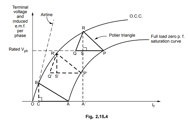
In
this graph, the distances RS, R' S' and BC are assumed equal. This represents
the voltage drop across the leakage reactance which is (Iaph)FL × XLph-
This indicates that the point P in the zero power factor test and point A in
the short circuit test represent same leakage reactance of the machine. But
this is not true as the excitation under short circuit condition is OA while
that for point P is OA' as shown. Now the excitation OA' is much higher than OC
and hence point P corresponding to saturated conditions represents larger
leakage flux which in the method assumed unchanged. Hence practically the
leakage reactance corresponding to saturated conditions is higher than that
assumed in the method. This introduces the error in the calculations
Example
2.15.1 A 10 kVA, 440 V, 50 Hz, 3 phase star connected
alternator has the open circuit characteristics as given below :
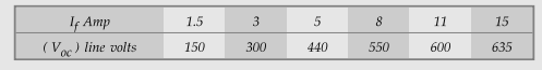
With
full load zero p.f, the applied excitation required is 14 A to produce 500 V of
terminal voltage. On short circuit, 4 A excitation is required to give full
load current. Determine the voltage regulation for full load, 0.8 p.f. lagging
and leading.
Solution
:
Convert
the given open circuit line voltages to phase voltages.

For
zero p.f. saturation curve two points are given. One is short circuit full load
current excitation of 4 A and terminal voltage zero. This is point A (4 A, 0 V)
on x-axis. Second point If = 14 A required to get 500 V line voltage at
terminals.
This
gives point P (14 A, 500 / √ 3 = 288.67 V). The O.C.C. and Potier triangle is
shown in the Fig. 2.15.5

From
Potier triangle PQR, the armature leakage reactance drop is I (RS) = 1.1 cm.
Iph × XLph = l(RS) × scale =
1.1 × 50 = 55 V
Case
i) : cos ϕ = 0.8 lagging
Find
E1 ph by adding vectorially Iph XLph to Vph
as shown.

Elph
= 290.382 V
From
O.C.C., corresponding Ffl = 6.1 A
From
potier triangle, field current balancing armature reaction is l (PS).
FAR
= l(PS) × scale = 3.1 × 1 = 3.1 A
Add
vectorially, Ffl and FAR as shown in the Fig. 2.15.7.
Using cosine rule for triangle,

The
corresponding voltage to FR = 8.33 A is equal to,
Eph
= 328 V ... from O.C.C.

Case
ii) : cos ϕ = 0.8 leading
The
drop Iph XLph remains same, only its direction changes
due to leading p.f. current. Find Elph by adding Iph XLph
to Vph as shown in the Fig. 2.15.8.
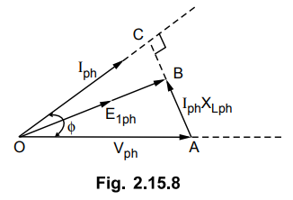
In
triangle OBC,
(Elph)2
= (OC) 2 + (BC) 2 = (Vph cos ϕ) 2 +
(Vph sin ϕ - Iph XLph)2
=
(254.03 × 0.8)2 + (254.03 × 0.6 - 55)2
Elph
= 225.366 V
From
O.C.C., corresponding to Elph, Ffl = 4.1 A
FAR
= 3.1 A remains same, from Potier triangle
Add
vectorially Ffl and FAR to get FR, as shown in
the Fig. 2.15.9.

Applying
cosine rule to ∆ OAB,
(FR)2
= (Ffl) 2 + (FAR) 2 -2Ffl FAR
cos(90- ϕ)
=
(4.1)2 + (3.1)2 - 2 × 4.1 × 3.1× cos (90 - 36.86)
FR
= 3.34 A
The
corresponding open circuit voltage to FR = 3 .34 A is equal to,
Eph
= 90 V

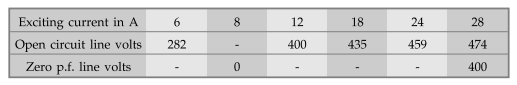
Example
2.15.2 A 11 kV, 1000 kVA, 3 phase, star connected alternator
has a resistance of 2 Ω per phase. The open circuit and full load zero power
factor characteristics are given below. Find the voltage regulation of the
alternator for full load current at 0.8 pf. lagging by using Potier method.
Solution
:
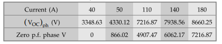
The given open circuit voltages are line values hence while sketching O.C.C. convert
to phase by dividing each by 1/√3
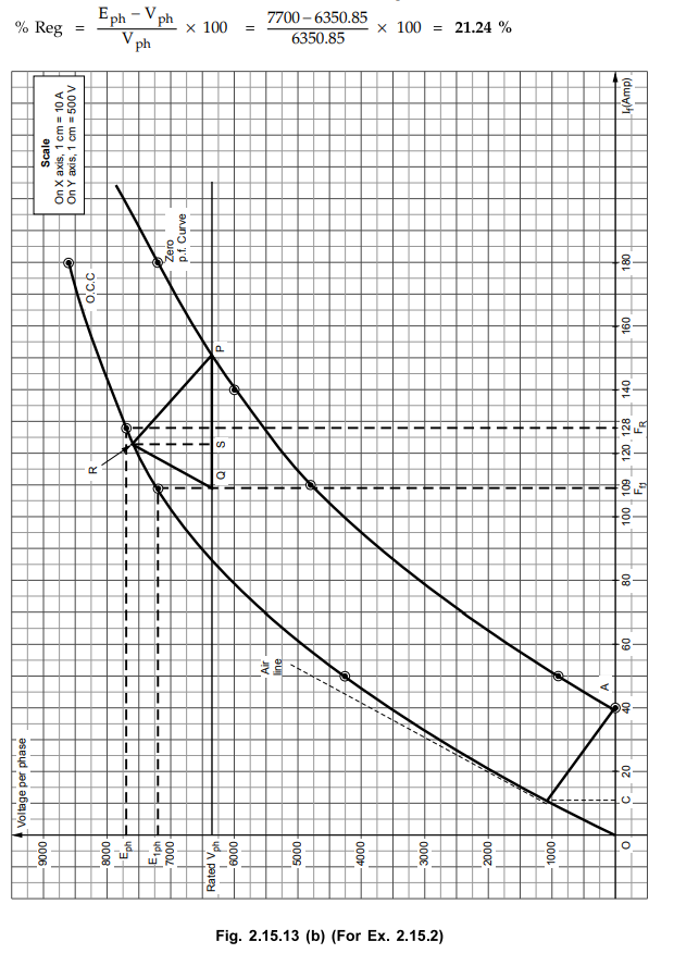
From
Potier triangle PQR, shown in Fig. 2.15.13 (b), the armature leakage reactance
drop is l(RS) = 2.4 cm

From
O.C.C., Ff1 = 109 A
The
field current for balancing armature reaction can be obtained from Potier
triangle which is length PS.
FAR
= l (PS) × Scale = 2.8 × 10 = 28 A
Adding
vectorially Ff1 and FAR as shown in Fig. 2.15.13 (a).
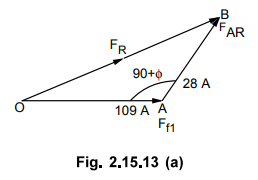
Using
cosine rule for A OAB,
(OB)2
= (OA) 2 + (AB) 2 -2(OA) (AB) cos (OA AB)
(FR)
2 = (Ff1) 2 + (FAR) 2 -2 (Ff1)
(FAR) cos (90 + ϕ)
=
(109) 2 + (28) 2 - 2 (109) (28) cos (90 + 36.86°)
(FR)
2 = 11881 + 784 - 6104 × (- 0.5998)
FR
= 127.77 A
From
O.C.C. shown in the Fig. 2.15.13 (b), the corresponding E ph is 7700
for FR = 127.77 A
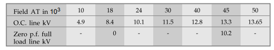
Example 2.15.3 The following data were obtained for the OCC of a 10 MVA, 13 kV, 3-phase 50 Hz, Y-connected synchronous generator.

An
excitation of 100 A causes the full-load current to flow during the
short-circuit test. The excitation required to give the rated current at zero
pf and rated voltage is 290 A.
i)
Calculate the adjusted synchronous reactance of the machine.
ii)
Calculate the leakage reactance of the machine assuming the resistance to be
negligible.
iii)
Determine the excitation required when the machine supplies full-load at 0.8 pf
lagging by using the leakage reactance and drawing the mmf phasor diagram. What
is the voltage regulation of the machine ? Also calculate the voltage
regulation for this loading using the adjusted synchronous reactance. Compare
and comment upon the two results. AU : May-16, Marks 16
Solution
:
10 MVA, 13 kV, 50 Hz, star connection
Ia(rated)
= VA/√3VL = 10 × 106 /√3 × 13 ×103 = 444 A
i)
Draw O.C.C. and S.C.C. as shown in the Fig. 2.15.14.

Note
that in graph line values of Voc are used.
For
rated voltage of 13 kV, calculate short circuit current from S.C.C. Corresponding
to 13 kV on O.C.C. shown by point M, the short circuit current is Isc
= 690 A from graph.

ii)
To find the leakage reactance, the potier triangle method must be used.
Plot
the O.C.C. and locatiob of point P corresponding to ZPF at rated current. The
point P is (290 A, 13 kV). This is shown in the Fig.2.15.14. Mark point A
corresponding to If = 100 A for circulating rated Isc .
Draw line PQ = OA parallel to OA from P and locate point Q. from Q, draw line
parallel to air line which intersects O.C.C. at R. Join PR. The triangle PQR is
the Potier is the triangle. Draw a line RS perpendicular from R on PQ. The
length RS gives the voltage drop due to the armature leakage reactance. i.e. IXL.

iii)
The length PS gives If necessary to overcome armature reaction.
l
(PS)
= FAR = 3.6 cm = 90 A … from graph
Now cos ϕ = 0.8 lagging
Find
Elph by adding vectorially (Iaph XLph) to Vph.
Consider
triangle OAB shown in the Fig. 2.15.14 (a).

From
graph of O.C.C., field curent corresponding to E1(line) = 13.7533 kV
is Ffl = 180 A
Add
vectorially Ffl and FAR as shown in the Fig. 2.15.14 (b).
Using cosine rule for the triangle OAB with

Use
modified air line to obtain If corresponding to 19.22 kV which is
line joining origin and point M. This gives linear relation between E(line) and
If. Thus for M, E1 (line) = 13 kV, I f = 156 A
hence for E1(line) = 19.22 kV, If = 19.22 / 13 × 156
230.64 A.
From
O.C.C., Eph = 14.8 kV for If = 230.64 A .
%Reg.
= 14.81-13 / 13 × 100 = 13.84 %
Examples
for Practice
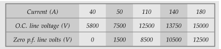
Example
2.15.4 The following table gives the open circuit and
full load zero p.f. saturation characteristics data for 40 kVA, 400 V, 3 phase,
50 Hz, star connected alternator :
Find
the values of armature reaction (in equivalent field current) and armature
leakage reactance. Also determine the voltage regulation at 0.8 lagging pf.
Neglect armature resistance.
[Ans.:
1.776 Ω 6.9 A, 20.49 A, 15.8 %]
Example
2.15.5 The following figures give the open circuit and
full load zero pf.
saturation
curves for a 15000 kVA, 11000 V, 3 phase, 50 Hz, star connected
turboalternator.
Find
the armature reaction, the armature reactance and the synchronous reactance.
Deduce the regulation for full load at 0.8 pf. lagging. JNTU
: March-06, Nov.-07, Feb.-08
[Ans.:
0.984 Q 6.16 Q 20.45 %]
Review Questions
1. Explain the potier method (ZPF) of determining the regulation
of an alternator.
AU : May-12,13,17,18, Dec.-06, 08, Marks 10
2. Define regulation and explain effect of power factor on
regulation. Using ZPF method, calculate regulation of given alternator. Mention
the advantages of this method over the other methods.
Electrical Machines II: UNIT I: b. Armature Reaction and Regulation of Alternators : Tag: Engineering Electrical Machines - II : Synchronous Generator or Alternators - Potier's Triangle Method or Zero Power Factor (ZPF) Method
Related Topics
Related Subjects

Electrical Machines II
EE3405 Machine 2 EM 2 4th Semester EEE Dept | 2021 Regulation | 4th Semester EEE Dept 2021 Regulation