Linear Integrated Circuits: Unit V: Application ICs
Power Amplifiers
Classification, Operating working principle, Features, Waveform circuit
The power amplifier is basically used to amplify an audio signal faithfully. The loads to such amplifiers are generally loud speakers and servomotors. Such loads require large current and sufficient power, typically few watts to tens of watts.
Power Amplifiers
April-03,
May-03,12
In
general, an amplifier receives an input signal from some transducer or other
input source and provides a large amplified signal to some output device or
another amplifier stage. The small signal amplifiers are basically voltage
amplifiers, the voltage and current signal levels are small in such amplifiers.
The output current capability of such amplifiers is limited. The amount of
power handling capacity and power efficiency are of little concern for the
small signal amplifiers.
The
power amplifier is basically used to amplify an audio signal faithfully. The
loads to such amplifiers are generally loud speakers and servomotors. Such
loads require large current and sufficient power, typically few watts to tens
of watts. Such power amplifiers develop and feed the sufficient power to the
loads like speakers, motors etc. by handling the large signals hence these are
also called as large signal amplifiers or power amplifiers. The low output
impedance is another requirement of such loads which is to be satisfied by the power
amplifiers.
Thus
the main features of a large signal amplifier or an power amplifier are,
i)
The large amount of power to be delivered to the load.
ii)
The power efficiency.
iii) The impedance matching to the output
device.
The
large signal amplifiers develop an a.c. power of the order of few watts.
Similarly large power gets dissipated in the form of heat, at the junctions of
the transistors used in the power amplifiers. Hence the transistors used in
such amplifiers are power transistors with heat sinks.
1. Classification of Power Amplifiers
The
power amplifiers are classified by their classes of operation. The class of
operation represents the amount of the output signal varies over one cycle of
operation for a full cycle of input signal.
For
an amplifier, a quiescent operating point (Q point) is fixed by selecting the
proper d.c. biasing to the transistors used. The position of the Q point on the
load line decides the class of operation.
a.
Class A Amplifiers
The
power amplifier is said to be class A amplifier if the Q point and the input
signal are selected such that the output signal is obtained for a full input
cycle. For this, position of the Q point is approximately at the midpoint of
the load line.
For
all values of input signal, the transistor remains in the active region and
never enters into cut-off or saturation region. When an a.c. input signal is
applied, the collector voltage varies sinusoidally hence the collector current
also varies sinusoidally. The collector current flows for 360° (full cycle) of
the input signal. In other words, the angle of the collector current flow is
360° i.e. one full cycle.
The
current and voltage waveforms for a class A operation are shown with the help
of output characteristics and the load line, in the Fig. 5.14.1.
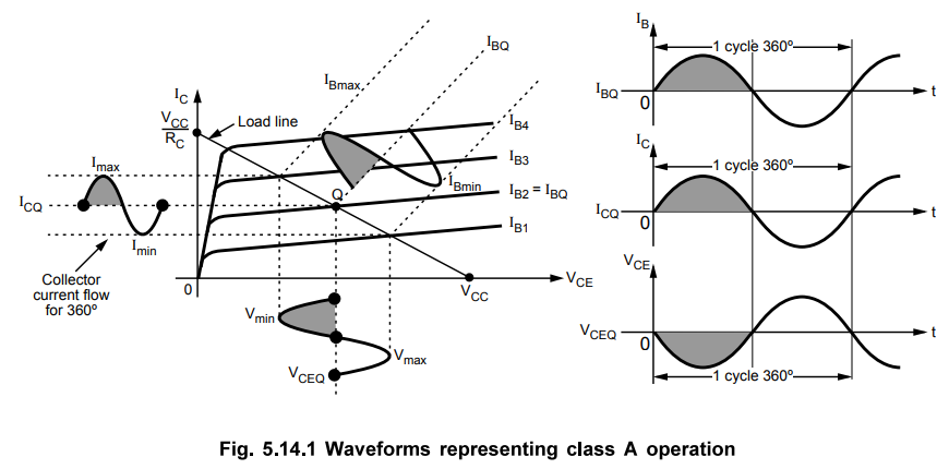
As
shown in the Fig. 5.14.1, for full input cycle, a full output cycle is
obtained. Here signal is faithfully reproduced, at the output, without any
distortion. This is an important feature of a class A operation. The efficiency
of class A operation is very small.
b.
Class B Amplifier
The
power amplifier is said to be class B amplifier if the Q point and the input
signal are selected, such that the output signal is obtained only for one half
cycle for a full input cycle. For this operation, the Q point is shifted on
X-axis i.e. transistor is biased to cut-off.
Due
to the selection of Q point on the X-axis, the transistor remains, in the
active region, only for positive half cycle of the input signal. Hence this
half cycle is reproduced at the output. But in a negative half cycle of the
input signal, the transistor enters into a cut-off region and no signal is
produced at the output. The collector current flows only for 180° (half cycle)
of the input signal. In other words, the angle of the collector current flow is
180° i.e. one half cycle.
The
current and voltage waveforms for a class B operation are shown in the Fig.
5.14.2.
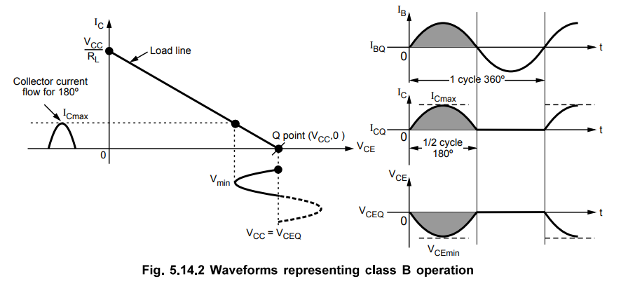
As
only a half cycle is obtained at the output, for full input cycle, the output
signal is distorted in this mode of operation. To eliminate this distortion,
practically two transistors are used in the alternate half cycles of the input
signal. Thus overall a full cycle of output signal is obtained across the load.
Each transistor conducts only for a half cycle of the input signal.
The
efficiency of class B operation is much higher than the class A operation.
c.
Class C Amplifier
The
power amplifiers is said to be class C amplifier, if the Q point and the input
signal are selected such that the output signal is obtained for less than a
half cycle, for a full input cycle. For this operation, the Q point is to be
shifted below X-axis.
Due
to such a selection of the Q point, transistor remains active, for less than a
half cycle. Hence only that much part is reproduced at the output. For remaining
cycle of the input cycle, the transistor remains cut-off and no signal is
produced at the output. The angle of the collector current flow is less than
180°.
The
current and voltage waveforms for a class C amplifier operation are shown in
the Fig. 5.14.3.
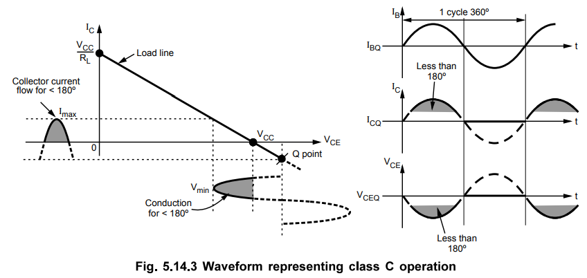
In
class C operation, the transistor is biased well beyond cut-off. As the
collector current flows for less than 180°, the output is much more distorted
and hence the class C mode is never used for A.F. power amplifiers. But the
efficiency of this class of operation is much higher and can reach very close
to 100 %.
d.
Class AB Amplifier
The
power amplifier is said to be class AB amplifier, if the Q point and the input
signal are selected such that the output signal is obtained for more than 180°
but less than 360°, for a full input cycle. The Q point position is above
X-axis but below the midpoint of a load line. The current and voltage waveforms
for a class AB operation, are shown in the Fig. 5.14.4.
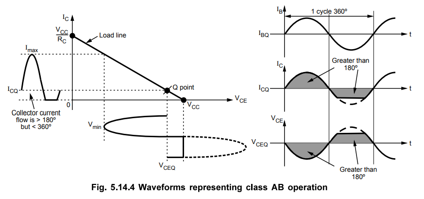
The
output signal is distorted in class AB operation. The efficiency is more than
class A but less than class B operation. The class AB operation is important to
eliminate cross over distortion.
In
general as the Q point moves away from the centre of the load line below
towards the X-axis, the efficiency of class of operation increases.
2. Comparison of Amplifier Classes
The
comparison of various amplifier classes is summarized in Table 5.14.1.
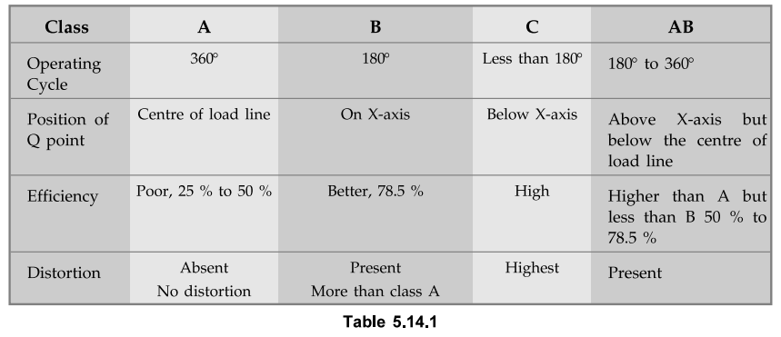
It
is important to note that class C operation is never used for audio frequency
amplifiers. This class is used in special areas of timed circuits, such as
radio or communications.
The
variety of monolithic as well as hybrid power amplifiers are commercially
available and very commonly used now a days. Let us study some examples of IC
audio power amplifiers, which are commercially available.
Review Question
1. Write an explanatory note on power amplifier.
Linear Integrated Circuits: Unit V: Application ICs : Tag: : Classification, Operating working principle, Features, Waveform circuit - Power Amplifiers
Related Topics
Related Subjects

Linear Integrated Circuits
EE3402 Lic Operational Amplifiers 4th Semester EEE Dept | 2021 Regulation | 4th Semester EEE Dept 2021 Regulation