Electrical Machines II: UNIT III: a. Three Phase Induction Motor
Power Flow in an Induction Motor
The various stages in this conversion is called power flow in an induction motor.
Power Flow in an Induction Motor AU : May-05, 07, 10,
12, 13, Dec.-06, 07, 08, 10, 14
Induction
motor converts an electrical power supplied to it into mechanical power. The
various stages in this conversion is called power flow in an induction
motor.
The
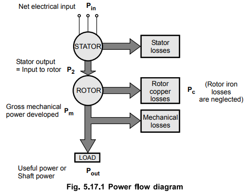
three phase supply given to the stator is the net electrical input to
the motor. If motor power factor is cos 0 and VL , IL are line values of supply
voltage and current drawn, then net input electrical power supplied to the
motor can be calculated as,
Pin
= √3 VL, IL cos ϕ
where
Pin = Net input electrical power
This
is nothing but the stator input.
The
part of this power is utilized to supply the losses in the stator which are
stator core as well as copper losses.
The
remaining power is delivered to the rotor magnetically through the air gap with
the help of rotating magnetic field. This is called rotor input denoted as P2.
So
P2 = Pin - Stator losses (Core + Copper)
The
rotor is not able to convert its entire input to the mechanical as it has to
supply rotor losses. The rotor losses are dominantly copper losses as
rotor iron losses are very small and hence generally neglected. So rotor losses
are rotor copper losses denoted as
So 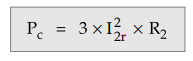
Where
I2r = Rotor current per
phase in running condition
R2
= Rotor resistance per phase
After
supplying these losses, the remaining part of P2 is converted into mechanical
which is called gross mechanical power developed by the motor denoted as
Pm.
Pm = P2 - Pc
Now
this power, motor tries to deliver to the load connected to the shaft. But
during this mechanical transmission, part of Pm is utilized to
provide mechanical losses like friction and windage.
And
finally the power is available to the load at the shaft. This is called net
output of the motor denoted as Pout. This is also called shaft
power.
Pout
= Pm - Mechanical losses
The
rating of the motor is specified interms of value of Pout when load
condition is full load condition
The
above stages can ben shown diagrammatically called power flow diagram of
an induction motor.
This
is shown in the Fig.5.17.1.
From the power flow diagram we can define,
1. Relationship between P2, Pc and Pm
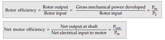
The
rotor input P2, rotor copper loss Pc and gross mechanical
power developed Pm are related through the slip s. Let us derive
this relationship.
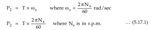
Let T = Gross torque developed by motor in N-m.
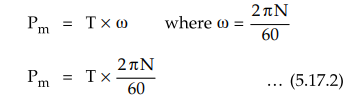
We
know that the torque and power are related by the relation,
P
= T × w
where
P = Power
and
w = Angular speed = 2π N / 60 = Speed in r.p.m.
Now
input to the rotor P2 is from stator side through rotating magnetic
field which is rotating at synchronous speed Ns.
So
torque developed by the rotor can be expressed interms of power input P2 and
angular speed at which power is inputted i.e. ws as,
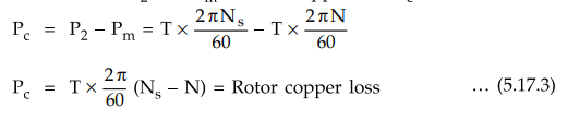
The
rotor tries to deliver this torque to the load. So rotor output is gross
mechanical power developed Pm and torque T. But rotor gives output at speed N
and not Ns. So from output side pm and T can be related through angular speed w
and not ws.
The
difference between P2 and pm is rotor copper loss Pc
Dividing
equation (5.17.3) by equation (5.17.1)
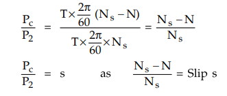
Rotor
copper loss Pc = s × Rotor input P2
Thus
total rotor copper loss is slip times the rotor input.
Now
P2-Pc = Pm
P2
- s P2 - Pm
(1
- s) P2 = Pm
Thus
gross mechanical power developed is (1 - s) times the rotor input. The
relationship can be expressed in the ratio form as,
P2
: Pc : Pm is 1 : s : 1 - s
The
ratio of any two quantities on left hand side is same as the ratio of
corresponding two sides on the right hand side.
For
example, Pc / Pm = s / 1 – s, P2 / Pc
= 1/s and so on.
This
relationship is very important and very frequently required to solve the problems
on the power flow diagram.
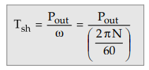
Key Point The
torque produced by rotor is gross mechanical torque and due to mechanical losses
entire torque cannot be available to drive load. The load torque is net
output torque called shaft torque or useful torque and is denoted
as Tsh- It is related to Pout as,
and
Tsh < T due to mechanical losses
Derivation
of k in Torque Equation
We
have seen earlier that
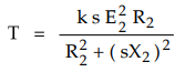
and
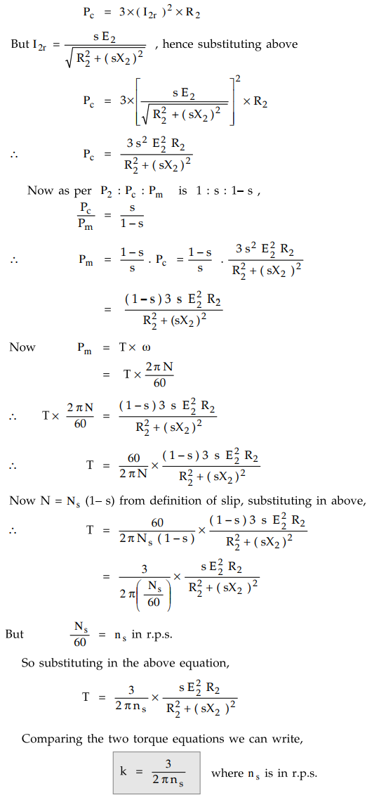
it is mentioned that k = 3 /2πns Let us see its proof.
The
rotor copper losses can be expressed as,
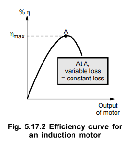
2. Efficiency of an Induction Motor
The
ratio of net power available at the shaft (Pout) and the net
electrical power input (Pin) to the motor is called as overall
efficiency of an induction motor.
%ƞ
= Pout / Pin × 100
The
maximum efficiency occurs when variable losses become equal to constant losses.
When motor is on no load, current drawn by the motor is small. Hence efficiency
is low. As load increases, current increases so copper losses also increase.
When such variable losses achieve the same value as that of constant losses,
efficiency attains its maximum value. If load is increased further, variable
losses become greater than constant losses hence deviating from condition for
maximum, efficiency starts decreasing. Hence the nature of the curve of
efficiency against output power of the motor is shown in the Fig. 5.17.2.
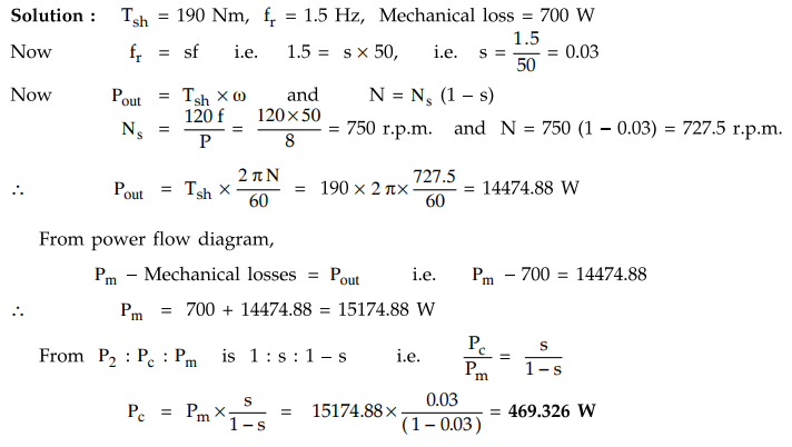
Example
5.17.1 The useful torque of a 3 phase, 50 Hz, 8 pole
induction motor is 190 Mn. The rotor frequency is 1.5 Hz. Calculate the rotor
copper losses if mechanical losses are 700 walts.
Example
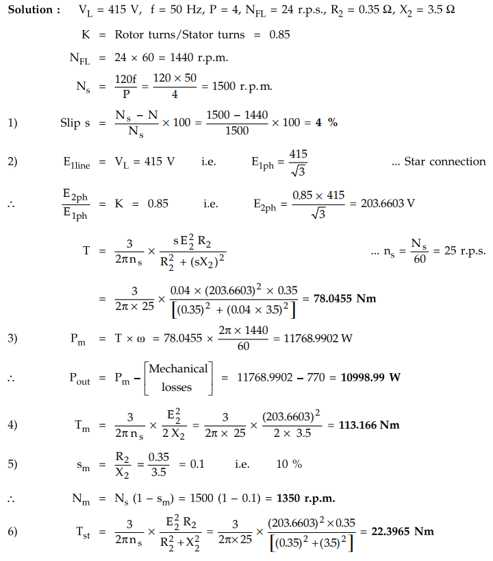
5.17.2 A 415 V, 3 phase, 50 Hz, 4 pole, star connected
induction motor runs at 24rev/s on full load. The rotor resistance and
reactance per phase are 0.35 ohm and 3.5 ohm
respectively and the effective rotor-stator turns ratio is 0.85 : 1. Calculate :
1)
Slip
2)
The full load torque
3)
The power output if the mechanical losses amount to 770 W
4)
The maximum torque
5)
The speed at which the maximum torque occurs and
6)
The starting torque.
Solution
:
Example
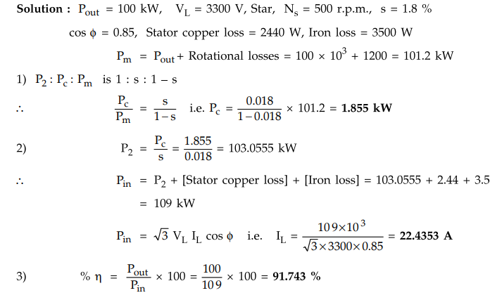
5.17.3 A 100 kW (output), 3300 V, 3 phase, star
connected induction motor has a synchronous speed of 500 r.p.m. The full load
slip is 1.8 % and full load power factor 0.85. Stator copper loss - 2440 W.
Iron loss - 3500 W. Rotational losses - 1200 W. Calculate 1) The rotor copper
loss 2) The line current 3) The full load efficiency. AU : Dec.-07, Marks 8
Solution
:
Example
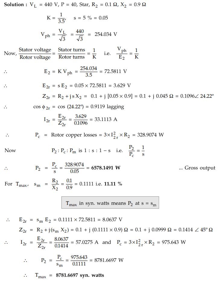
5.17.4 A 3 phase, 440 V, 50 Hz, 40 pole, Y-connected
induction motor has rotor resistance of 0.1 Ω and reactance 0.9 Ω
per phase. The ratio of stator to rotor turns is 3.5. Calculate gross output at
a slip of 5 %, and the maximum torque in syn. watts and corresponding slip.
Solution
:
Example
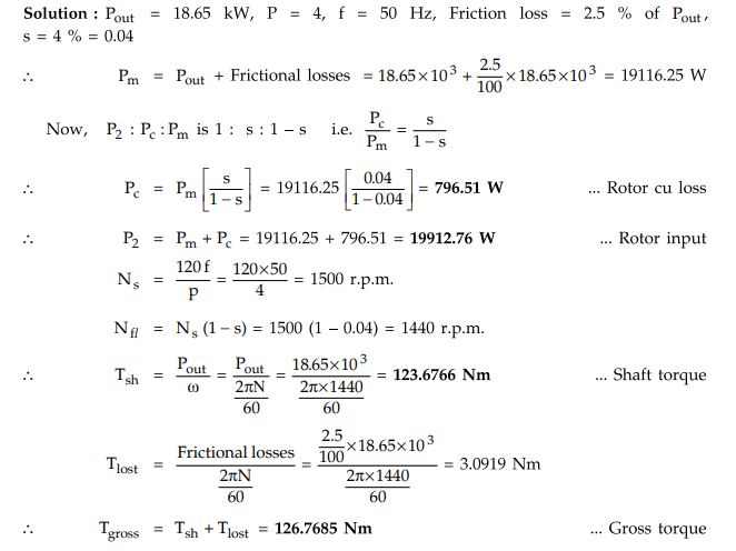
5.17.5 An 18.65 kW, 4 pole, 50 Hz, 3 phase induction motor
has friction and windage losses of 2.5 percent of the output. Full load slip is
4 %. Find for full load 1) Rotor copper loss 2) Rotor input 3) Shaft torque 4)
the gross electromagnetic torque. AU : Dec.-06, 10, Marks
8
Solution
:
Example
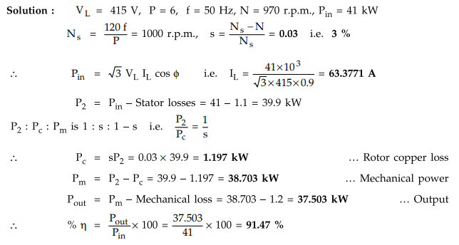
5.17.6 The real power input to a 415 V, 50 Hz, 6 pole,
3-phase induction motor running at 970 rpm is 41 kW. The input power factor is
0.9. The stator losses amount to 1.1 kW and the mechanical losses total 1.2 kW.
Calculate the line current, slip, rotor copper loss, mechanical power output
and efficiency.
Solution
:
Example
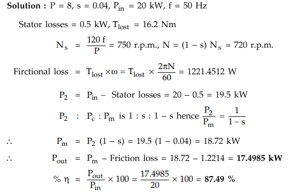
5.17.7 An eight pole, 3-phase induction motor running with
the slip of 4 % takest 20 kW from a 50 Hz supply. Stator losses amount to 0.5
kW. If the mechanical torque lost in friction is 16.2 Nm. Find the power output
and efficiency.
Solution
:
P = 8, s = 0.04, Pin = 20 kW, f =
50 Hz
Stator
losses = 0.5 kW, Tlost = 16.2 Nm
Example
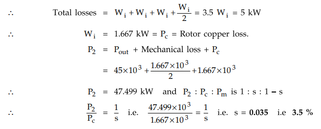
5.17.8 An induction motor has an efficiency of 0.9 when the
shaft load is 45 kW. At this load, stator ohmic loss and rotor ohmic loss each
is equal to the iron loss. The mechanical loss is one-third of the no-load
losses. Neglect ohmic losses at no-load. Calculate the slip.
Solution
:
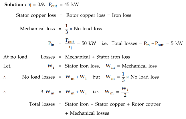
Rotor
iron losses are negligible due to low rotor frequency.
Stator
copper loss = Rotor copper loss = Stator
iron loss = Wi
Examples
for Practice
Example
5.17.9 The power input to a 3 phase 50 Hz induction
motor is 50 kW. The total stator loss is 800 W. Find the total mechanical power
developed, if the rotor emf makes 90 complete cycles per minute.
[Ans.:
Pm = 47724 W]
Example
5.17.10 A 6-pole, 50 Hz, 3-^ induction motor running on
full load develops a useful torque of 150 Nm at a rotor frequency of 1.5 Hz.
Calculate the shaft power output. If the mechanical torque lost in friction be
10 Nm, determine: i) Rotor copper loss ii) The input to the motor iii) The
efficiency.
[Ans.:
i) 502.6548 W, ii) 17455.16 W, iii) 87.29 %]
Example
5.17.11 A 3 phase, 4 pole, 50 Hz, star connected
induction motor running on full load develops a useful torque of 300 N-m. The
rotor e.mf. is completing 120 cycles per minute. If torque lost in friction is
50 Nm, calculate : i) Slip ii) Net output power iii) Rotor copper loss per
phase iv) Rotor efficiency and v) Rotor resistance per phase if rotor current
is 60 A in running condition.
[Ans.:
i) 4 %, ii) 45.2389 kW, iii) 733.0378 W, iv) 96 %, v) 0.2036 n/ph]
Example
5.17.12 A 3 phase, 4 pole, 50 Hz induction motor is
supplied by 400 V supply. Its full load slip is 4 %. At full load, stator
copper losses are same as rotor copper losses. Stator iron losses are 25 % more
than stator copper losses. Mechanical losses are one third of no load losses.
Full load output is 50 h.p. Calculate the efficiency on full load.
[Ans.:
% ^ = 85.77 %]
Example
5.17.13 An I.M. has an efficiency of 0.9 when the load
is 50 H.P. At this load, stator copper loss and rotor copper loss is each equal
to the iron loss. The mechanical losses are one-third of the no load losses.
Calculate the slip.
[Ans.:
s = 0.03 i.e. 3 %]
Example
5.17.14 A squirrel-cage induction motor is rated 25 kW,
440 V, 3-0, 50 Hz. On full-load it draws 28.7 kW with line current 50 A and
runs at 720 rpm. Calculate :
i)
The slip (s) ii) The power factor, and iii) The efficiency (ƞ). UPTU
: 2013-14
[Ans.:
i) 4 %, ii) 0.7532 lagging, iii) 87.108 %]
Example
5.17.15 A3- ϕ, 400 V, 6-pole, 50Hz,
IM, develops mechanical power of 20 kW at 985 rpm. Calculate :
i)
The rotor copper loss, ii) The total input power, and iii) Rotor frequency (f2)
The
stator losses are equal to 1800 W. Neglect mechanical loss.
UPTU
: 2013-14
[Ans.:
i) Pc = 0.3045 kW, ii) Pin = 22.1045 kW, iii) f2
= 0.75 Hz]
Example
5.17.16 A 25 kW, 4 pole, 3 phase, 50 Hz
induction motor is running at 1410 r.p.m., supplying full load. The mechanical
losses are 850 W and stator losses are 1.7 times rotor copper losses on full
load. Calculate ,
i)
Gross mechanical power developed
ii)
Rotor copper losses
iii)
The value of rotor resistance per phase if rotor current on full load per phase
is 65 A
iv)
The full load efficiency.
[Ans.:
25850 W, 1650 W,0.13 n per phase, 82.49 %]
Example
5.17.17 A 6 pole 50 Hz, 3 phase, induction motor running
on full load with 4 % slip develops a torque of 149.3 Nm at its pully rim. The
friction and windage losses are 200 W and the stator copper and iron losses are
equal to 1620 W. Calculate :
i)
Output power ii) The rotor copper losses iii) The efficiency at full load.
VTU
: July-11, Aug.-05
[Ans.
: 15209.2 W, 633.7166 W, 87.094 %]
Example
5.17.18 A 6 pole, 3-phase induction motor develops 30 HP
including mechanical losses, total 2 HP at a speed of 950 rpm on 550 V, 50 Hz
mains. The power factor is 0.58. Calculate for this load i) slip ii) the rotor
copper loss iii) the total input if the stator losses are 2000 W iv) the
efficiency v) the line current vi) the number of complete cycles of the rotor
e.m.f. per minute.
[Ans.:
5 %, 1238.736 W, 26774.736 W, 82.409 %, 31.938 A, 150 cycles/min]
Example
5.17.19 A 25 HP, 6 pole, 50 Hz, slip ring induction
motor runs at 960 rpm on full load, with a rotor current of 35 A. Allowing 250
W for the copper loss in the short circuiting gear and 1000 W for mechanical
losses, find the resistance per phase of the 3-phase rotor winding.
[Ans.
: 0.1546 Ω]
Review Questions
1. Discuss the different power stages of a 3 phase induction
motor with losses with the help of a power flow diagram.
2. Derive the relation between refer input rotor copper losses
of mechanical power developed in terms of a slip of a three phase induction
motor.
Electrical Machines II: UNIT III: a. Three Phase Induction Motor : Tag: Engineering Electrical Machines - II : - Power Flow in an Induction Motor
Related Topics
Related Subjects

Electrical Machines II
EE3405 Machine 2 EM 2 4th Semester EEE Dept | 2021 Regulation | 4th Semester EEE Dept 2021 Regulation