Electrical Machines II: UNIT II: Synchronous Motor
Power Flow in Synchronous Motor
Net input to the synchronous motor is the three phase input to the stator.
Power Flow in Synchronous Motor
Net
input to the synchronous motor is the three phase input to the stator.
Pin
= √3 VL IL cosϕ W
where
VL = Applied line voltage
IL
= Line current drawn by the motor
cos
ϕ = Operating p.f. of synchronous motor
or
Pin = 3 (per phase power) = 3 × Vph Iaph cos ϕ
W
Now
in stator, due to its resistance Ra per phase there are stator
copper losses.
Total
stator copper losses = 3 × (Iaph)2 × Ra W
The
remaining power is converted to the mechanical power, called gross
mechanical power developed by the motor denoted as Pm.
Pin
= Pin - Stator copper
losses
Now P = T ×
W
Pm
= Tg × 2π NS / 60 a speed is always NS
Tg
= Pm × 60 / 2π NS
This
is the gross mechanical torque developed. In d.c. motor, electrical
equivalent of gross mechanical power developed is Eb × Ia,
similar in synchronous motor the electrical equivalent of gross mechanical
power developed is given by,
Pm
= 3 Ebph × Iaph
× cos (Ebph Λ Iaph)
i)
For lagging p.f., Ebph Λ
Iaph = ϕ - δ
ii) For lagging p.f., Ebph Λ Iaph =
ϕ + δ
iii) For unity p.f., Ebph Λ Iaph = δ
Note
:
While calculating angle between Ebph and Iaph from phasor
diagram, it is necessary to reverse Ebpb phasor. After reversing Ebpb, as it is
in opposition to Vph, angle between Ebph and Iaph
must be determined.
In
general,
Pm
= 3 Ebph Iaph cos (ϕ ± δ )
Positive
sign for leading p.f. and Negative sign for lagging p.f.
Net
output of the motor then can be obtained by subtracting friction and windage
i.e. mechanical losses from gross mechanical power developed.
Pout
= Pm - mechanical losses.
Tshaft = Pout × 60 / 2π
NS Nm
where
Tshaft = shaft torque available to load
Pout
= Power available to load
%
ƞ Pout / Pin × 100
… Overall efficiency
The
power flow in synchronous motors can be summarized as shown in the Fig. 4.13.1

Example
4.13.1 A 9 kW, 400 V three phase star connected synchronous
motor has synchronous impedance per phase of (0.4 + 3j) Ω. Find the angle of
retard and the voltage to which the motor must be excited to give a full-load
output at 0.8 leading power factor. Assume an efficiency of 90 %.
Solution
:
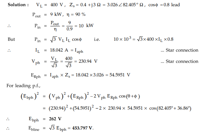
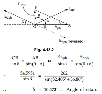
The
phasor diagram is shown in the Fig. 4.13.2.
To
find angle of retard δ , apply sine rule to ∆ OBA
Example
4.13.2 A three phase 500 V, star connected synchronous
motor gives net output of 17 kW on full load operating at 0.9 lagging power
factor. Its armature resistance is 0.8 Ω per phase. The mechanical losses are
1300 W. Estimate the current drawn by the motor and full load efficiency.
Solution
:

Example
4.13.3 A 75 kW, 400 V, 4-pole, 3-phase, star-connected
synchronous motor has a resistance and synchronous reactance per phase of 0.04
Ω and 0.4 Ω respectively. Compute for full load 0.8 pf lead the open-circuit
e.m.f. per phase and gross mechanical power developed. Assume an efficiency of
92.5 %.
Solution
:

Alternatively,
Pm = 3EbphIaph cos(ϕ + δ) for which δ must be
calculated. Students may calculate δ and use the above expression to calculate
Pm. For reference, δ = 10.89°.
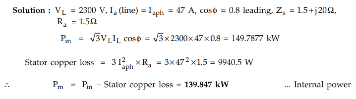
Example
4.13.4 A 3-phase star-connected synchronous motor rated at
187 kVA, 2300 V, 47 A, 50 Hz, 187.5 rpm has an effective resistance of 1.5 Ω
and a synchronous reactance of 20 Ω per phase. Determine the internal power
developed by the motor when it is operating at rated current and 0.8 power
factor leading.
Solution
:
Examples
for Practice
Example
4.13.5 A 6600 V, three phase, star connected
synchronous motor draws a full load current of 80 A at 0.8 pf. leading. The per
phase armature resistance is 2.2 Ω
and synchronous reactance is 22 Ω. If the stray losses of machine are 3200
watt, calculate the induced e.m.f, output power and efficiency. UPTU : 2005-06
[Ans.:
4962.1625 V, 686.1782 kW, 93.78 %]
Example
4.13.6 A 20-kW, 400-V, 3-phase, star-connected
synchronous motor has per phase impedance of (0.15 + j 0.90) Ω. Determine the
induced emf torque angle and mechanical power developed for full load at 0.8 pf
lagging. Assume 92 % efficiency of the motor. Draw phasor diagram.
[Ans.:
206.534 V, 6.1414°, 21.04 kW]
Review Question
1. Explain the power flow in synchronous motor with the help of
power flow diagram.
Electrical Machines II: UNIT II: Synchronous Motor : Tag: Engineering Electrical Machines - II : - Power Flow in Synchronous Motor
Related Topics
Related Subjects

Electrical Machines II
EE3405 Machine 2 EM 2 4th Semester EEE Dept | 2021 Regulation | 4th Semester EEE Dept 2021 Regulation