Transmission and Distribution: Unit II: (a) Modelling and Performance of Transmission Lines
Power Flow through Transmission Line
Short Transmission Line
The flow of power at any point along a transmission line can be determined with the knowledge of voltage, current and power factor.
Power Flow through
Transmission Line
AU : Oct.-98, May-10, 11, 15, Dec.-15,
17
The flow of power at any point along a transmission
line can be determined with the knowledge of voltage, current and power factor.
This power can be derived in terms of the transmission or ABCD parameters.
These equations can be applied to any two terminal pair network.
Fig. 2.14.1 shows a transmission line
with sending end quantities represented by subscript 'S' and receiving end
quantities represented by subscript 'R'.
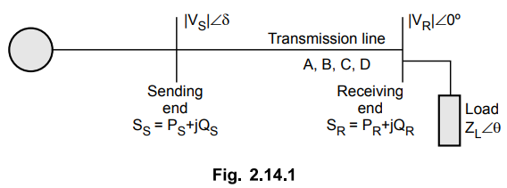
The complex power delivered by the
receiving end and that received by the sending end of the transmission line is
given as,
SR = PR + jQR
= VR IR
SS = PS + jQS
= VS IS
Here IR and IS are
complex conjugate of currents IR and IS.
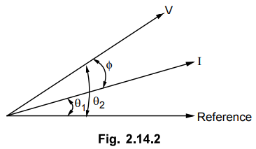
Consider the Fig. 2.14.2.
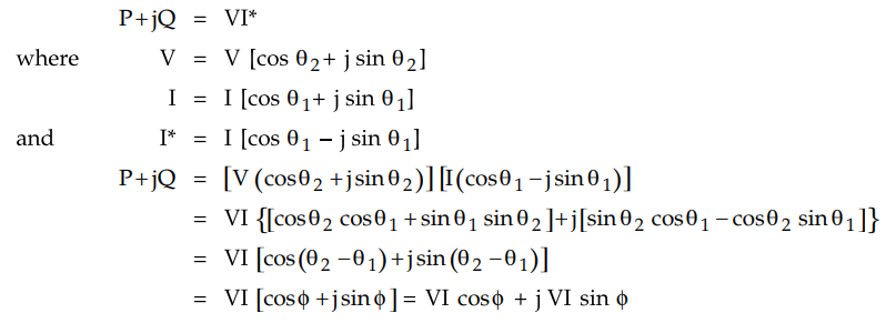
Consider the following equation for
sending end voltage in terms of ABCD parameters.
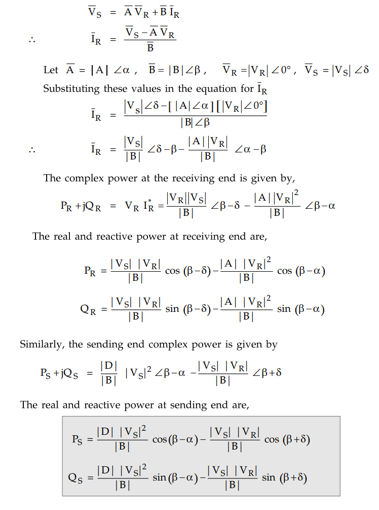
The receiving end power will be maximum
when P=8 as seen from above equation. Substituting β = δ in the expression for PR we
get
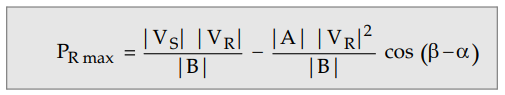
The corresponding QR when PR
is maximum is given by,
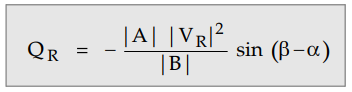
Thus maximum real power will be received
if the load draws the leading reactive power given by above equation.
Thus it can be seen that there is limit
to the power that can be transmitted to the receiving end of the line for
specified magnitudes of sending and receiving end voltages. When angle δ
becomes equal to β, maximum power will be transferred or delivered. Further increase
in δ results in less power received.
For achieving the condition of maximum
power the load must draw a large amount of leading current which is not
practicable. But by using leading VAR compensation the power transfer can be
improved.
1. Power Flow through Short Transmission Line
Consider a short transmission line with
series impedance Z. The shunt admittance of the line is negligible. The ABCD
parameters for short transmission line are
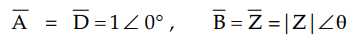
Substituting these values in expressions
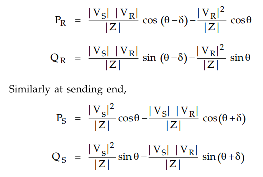
for PR and QR obtained in previous section we get,
The equations that are written for short
transmission line can also be applied for a long line when the line is replaced
by its equivalent n model and the shunt admittances are lumped with the load at
receiving end and sending end generation.
From the above equation for PR,
it can be seen that maximum power is received at receiving end when δ = θ such that
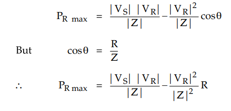
Normally resistance of a transmission
line is small as compared to its reactance which is necessary to maintain
efficiency of line high
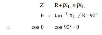
Thus by neglecting R the expressions for
PR and QR will reduce to
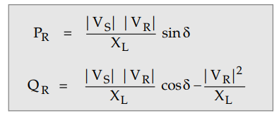
For stability considerations equation
for PR is helpful while equation for QR plays important
role in reactive power compensation.
In practice angle δ is between 15 to 30°
So that cos 8 lies between 0.966 and 0.866. If we assume 8 = 1 we will get
reactive power supplied by short line to receiving end as given by,
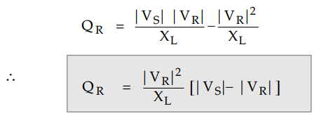
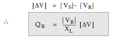
The difference between sending end and
the receiving end voltage is say AV
Various important observations can be
obtained which are as follows :
1. For small R (R ≅ 0) and for small δ,
the real power transferred to the receiving end is proportional to sin δ while
the reactive power is proportional to the magnitude of the voltage drop across
the line.
2. Maximum real power transferred is
maximum when δ = 90° and the magnitude of this maximum power is | VS |
|VR| /XL. sin= sin 90° = 1 is called steady state
stability limit.
3. Maximum power at receiving end is
proportional to V2. Hence for higher power transfer, corresponding voltage must
also be higher.
4. Reactive power delivered by line QR
is dependent on AV and is independent of power angle δ.
Consider the equation for a short
transmission line that we have already considered
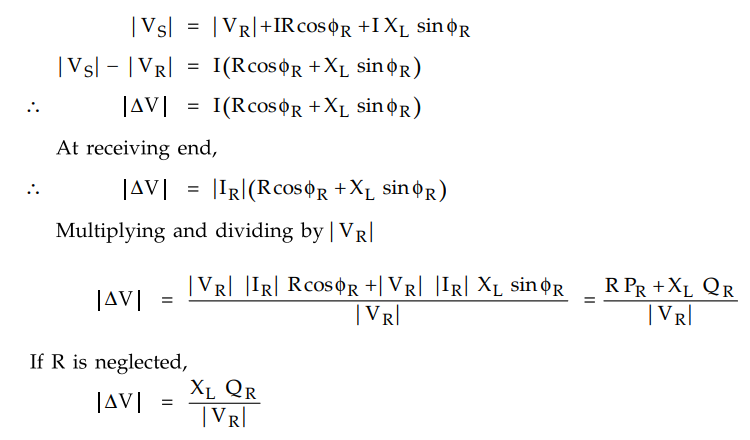
This expression we had obtained previously.
Thus the voltage drop | ΔV | in the line is determined by the series reactance
XL of the line and the reactive power delivered by the line at
receiving end i.e. QR.
If reactive power QR is
injected at receiving end, the line voltage drop | ΔV | can be reduced. This is
called reactive power compensation during high loads. From this equation it can
also be seen that larger power can be transmitted over a line with fixed
voltages by providing compensation at the receiving end.
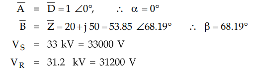
Example 2.14.1
The sending and receiving end voltages of a 3 phase transmission line are
maintained at 33 kV and 31.2 kV respectively. The resistance and reactance per
phase are 20 and 50 ohms respectively. Determine the maximum power obtainable
at the receiving end.
Solution :
Since the capacitance of the line is not mentioned it is neglected. Hence the
line is treated as short transmission line. The ABCD parameters are given by,
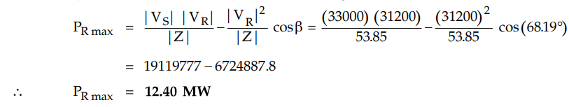
The expression for maximum power is
given by
Review Question
1. Deduce an expression for the sending end and receiving
end power of a line in terms of voltages and ABCD constants. Show that the real
power transferred is dependent on the power angle and reactive power
transferred is dependent on the voltage drop in the line.
AU : May-10, 11, 15, Dec.-15, 17, Marks 16
Transmission and Distribution: Unit II: (a) Modelling and Performance of Transmission Lines : Tag: : Short Transmission Line - Power Flow through Transmission Line
Related Topics
Related Subjects

Transmission and Distribution
EE3401 TD 4th Semester EEE Dept | 2021 Regulation | 4th Semester EEE Dept 2021 Regulation