Basic Civil & Mechanical Engineering: UNIT IV: a. Power plants
Power plants
Working Principle, Layout Diagram, Advantages, Disadvantages
Power plants are used for the generation of electric power from the various sources of energy. Fuel represents the largest operating expense in electric power generation. This Chapter deals with the utilization of energy resources to generate electricity in power plants.
UNIT – IV
Chapter - 11
POWER PLANTS
UTILIZATION OF ENERGY RESOURCES
Power
plants are used for the generation of electric power from the various sources
of energy. Fuel represents the largest operating expense in electric power
generation. This Chapter deals with the utilization of energy resources to
generate electricity in power plants.
THERMAL POWER PLANT
Working
Principle
A
Thermal Power Plant is also known as Steam Power Plant. It is using steam as the
working fluid. Superheated high pressure steam is generated in a Boiler using
coal as fuel. That is, Chemical Energy of coal is converted into Heat Energy of
steam by burning coal.
Heat
energy of steam is converted into Mechanical Energy by expanding the steam in a
Steam Turbine (Prime Mover). This mechanical energy is converted into Electrical
Energy in the Electrical Generator.
Fig.
1 shows the stages of energy transformation in a thermal power plant.

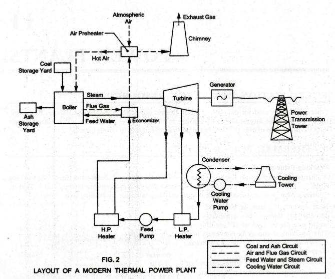
1. LAYOUT OF A MODERN THERMAL POWER PLANT
Fig.
2 shows the layout of a thermal power plant. It consists of Four Circuits.
These are:
1.
Coal and Ash Circuit
2.
Air and Flue Gas Circuit
3.
Feed Water and Steam Circuit
4.
Cooling Water Circuit
1.
Coal and Ash Circuit
Coal
from the mines is stored in the Coal Storage Yard. It is transferred to the
Boiler Furnace by means of coal handling equipment like belt conveyor, bucket
elevator, etc. Coal is burnt in the boiler furnace. Hot ash formed due to the
combustion of coal in the furnace is removed to the Ash Storage Yard by means
of ash handling equipment.
Ash
Disposal: Indian coal contains about 40% ash. A
power plant of 100 MW capacity produces about 25 tonnes of hot ash per hour.
Hence, sufficient space near the power plant is essential to dispose such large
quantities of hot ash.
2.
Air and Flue Gas Circuit
Air
is taken in from the atmosphere to Air Pre-heater. Air is heated in the air
pre-heater by the flue gases from the economizer. Then the hot air from the air
pre-heater is supplied to the furnace of the Boiler for combustion of coal.
Coal contains elements which get oxidized during reaction with Oxygen supplied
by air.
The
flue gases after combustion in the furnace, pass around the boiler tubes to
generate superheated steam. The flue gases then flow through an Economizer and
the Air Pre-heater.
Economizer:
The function of an economizer is to absorb the heat of the outgoing flue gases,
to raise the temperature of the feed water before it enters the boiler.
Finally,
the flue gases from air pre-heater are exhausted to the atmosphere through the
Chimney. By this method, the heat of the flue gases which would have been
wasted otherwise is used effectively in both the economizer and the air
pre-heater. Thus, the overall efficiency of the power plant is improved.
Air
Pollution
The
pollution of the surrounding atmosphere is caused by the emission of the
objectionable gases and dust through the chimney. The air pollution causes
nuisance to people surrounding the plant. In fact, air pollution is a health
hazard.
3.
Feed Water and Steam Circuit
Steam
Turbine
The
high pressure steam generated in the boiler is supplied to the Steam Turbine.
Work is done by the expansion of steam in the turbine. Hence, the pressure of
steam is reduced.
The
function of the steam turbine is to convert the heat energy in the steam into
rotational power of the shaft on which the turbine is supported. The rotational
speed of the turbine shaft is set by the frequency of the electricity supply
and is 3000 revolutions per minute (50 r.p.s.) corresponding to an alternating
electric supply at 50 hertz (c.p.s.).
Electric
Generator
The
electric generator is directly coupled to the turbine shaft. It converts the
mechanical energy of turbine shaft into electrical energy. It consists of two
electrical windings. One is mounted on the turbine shaft rotating with it, and
is called the Rotor. The other is arranged as a shroud around the rotor, fixed
to the floor and is called the Stator. The relative motion of rotor and stator
generates the electricity at 11,000 volts.
Condenser
The
expanded low pressure steam from the turbine passes to a Condenser, where it is
condensed to water by cooling. The condenser is a large vessel containing a
number of brass tubes. Cold water is circulated through these tubes
continuously for condensing the steam flowing outside the surface of the tubes.
The
condensate (i.e., condensed water) leaving the condenser is first heated in a
L.P. Water Heater by using the steam taken from the low pressure extraction
point of the turbine. Some of the steam and water is lost while passing through
different components of the system. Therefore, feed water is supplied by a Feed
Pump from an external source to compensate this loss. The external source of
water is used as a make-up to the feed water system.
Again,
steam taken from the high pressure extraction point of the turbine is used for
heating the feed water in the H.P. Water Heater. The hot feed water is passing
through the economizer, where it is further heated by the flue gases. The feed
water which is sufficiently heated by the L.P. and H.P. feed water heaters as
well as economizer is fed into the boiler.
4.
Cooling Water Circuit
The
condenser condenses the exhaust steam from the turbine to water by cooling. The
volume occupied by the condensate is very much less than that of the low
pressure steam. Thus, the pressure of the condensate reduces to vacuum. When
the exhaust steam is passed to the condenser, its pressure automatically drops
to vacuum that is existing in the condenser.
Hence,
the steam in the turbine expands to vacuum condenser pressure, instead of to
atmospheric pressure. This increase in the amount of pressure drop in the
turbine increases the amount of work done. Thus, the efficiency of the plant is
improved by the condenser by lowering the exhaust pressure of steam and also by
providing hot feed water to the boiler.
Abundant
quantity of cooling water (called coolant) is required for condensing the steam
in the condenser. The condensed water is reused in the cycle.
Water
circulating through the condenser may be taken from sources such as nearby
river or lake, provided adequate water supply is available from the river or
lake throughout the year. If adequate quantity of water is not available
at the plant site, the hot coolant from the condenser is cooled in the Cooling
Tower and re-circulated again.
Cooling
Tower
The
hot cooling water from the condenser passes on to the top of the Cooling Tower
from where it is sprayed downwards through nozzles. It is cooled in contact
with the atmospheric air entering along the periphery of the tower from the
bottom and traveling in the upward direction. The hot coolant gives up its heat
to the air. It becomes cool and is collected at the bottom of the tower. This
cold water is again circulated by coolant pump to the condenser.
2. ADVANTAGES
1.
Renewable Energy: Water is a natural recourse. It is a
renewable energy source. It is the cheapest source of energy. It is a free gift
by Nature.
2.
Low Initial Cost: Initial Cost is low compared with hydel
power plant.
3.
Location: The thermal power plant can be located near the
load center. Therefore, the transmission cost and transmission losses are
considerably reduced.
4.
The generation of power is not dependent on the nature's mercy like hydel
plant.
5.
Lesser Period of Time: The construction, erection and
commissioning of thermal plant requires lesser period of time than a hydel
plant.
3. DISADVANTAGES
1.
Non-renewable Source of Energy: The fuel (coal) used
in thermal plant will one day get ... exhausted by gradual use, since it is a
non-renewable source of energy.
2.
Part Load Efficiency: Its part load efficiency decreases very
rapidly with decreasing load.
3.
Transportation: Transportation of coal is difficult, if
the plant is located away from coal mines.
4.
Power Generation Cost: Power generation cost is high
compared with hydel plant.
5.
Air Pollution: Burning coal in the plant produces
smoke. The smoke is exhausted through the chimney into the atmosphere. This
causes air pollution.
6.
Life of the Plant: Life of the thermal power plant is
hardly about 30 - 40 years compared with the life of the hydel power plant
(i.e., about 100 – 125 years).
7.
Decrease in Efficiency: Efficiency of the plant decreases
to less than 10% after its life period.
8.
Running Speed: The turbines in thermal plant run at a
speed of 3000 to 4000 rpm. Therefore, they require special alloy steel
materials and rigid construction, compared to hydel plant which has a low
running speed of 300 to 400 rpm.
Basic Civil & Mechanical Engineering: UNIT IV: a. Power plants : Tag: : Working Principle, Layout Diagram, Advantages, Disadvantages - Power plants
Related Topics
Related Subjects

Basic Civil and Mechanical Engineering
BE3255 2nd Semester 2021 Regulation | 2nd Semester EEE Dept 2021 Regulation