Transmission and Distribution: Unit II: (a) Modelling and Performance of Transmission Lines
Power System Stability
Power Angle Diagram
The term stability with respect to the transmission line refers to the stable operation of the power system with sending end and receiving end terminals in synchronism with each other.
Power System Stability
AU : April-2000, Dec.-13
The term stability with respect to the
transmission line refers to the stable operation of the power system with
sending end and receiving end terminals in synchronism with each other. When
this synchronism is lost it is said to be the unstable operation. The stability
limit corresponds to maximum power flow possible without losing the stability.
Consider the generator supplying power
to the load through the transmission line as shown in Fig. 2.19.1.
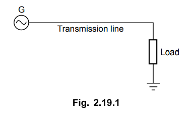
The load may consist of either
impedance, Load induction motor or
synchronous motor. With the load of the type static impedance, there is limit
for generator to supply power to the load but the system can never lose
synchronism or become unstable. Similarly for the induction motor there is
limit and it can become unstable only when motor stalls but it can never lose
the synchronism. But for synchronous motor type of load, it can cause
unstability and loss of synchronism.
Thus it is required that under steady
state and under dynamic conditions, the synchronism must be maintained.
The steady state stability limit refers
to maximum power transfer that is possible with small changes in power flow or
gradual disturbance, without losing stability. The transient stability refers
to the maximum power transfer that is possible for given amount of sudden or
large changes in power disturbance without loss of stability. The voltage
stability corresponds to limit on maximum power transfer through the
transmission line beyond which the voltage collapses and stability is lost.
1. Power Angle Diagram
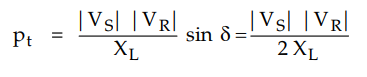
We have already seen that after
neglecting resistance and shunt admittance of the line the power at the
receiving end is given by,
PR = | VS | |VR
| / XL sin δ
The angle δ is called phase angle or the
torque angle or load angle between sending and receiving end voltages.
With increase in load, angle & also
increases. But it has limit beyond which power flow is not increased. This
upper limit is called stability limit. The variation of power flow with angle
& is shown in Fig. 2.19.2.
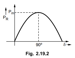
From the above equation it can be
clearly seen that when δ = 0, PR is also zero while when δ = 90°
then PR is maximum when 8 goes beyond 90°, PR goes on reducing and
at δ =180°, it reduces to zero.
When there is sudden change in
transmission system, change in load, tripping of generator or load, sudden
switching load, any fault etc. brings about oscillations in angle 8. If load
angle 8 goes beyond 90°, the synchronism is lost and the transmission system
fails to transfer the power. Pm is called steady state stability
limit and is given by,
Pm = | VS | |VR
| / XL
Transient state stability is one half of
steady state stability,
If the mechanical power input to the
alternator and the load on the system is unchanged for arbitrary disturbances,
the system returns to the stable working point. With large disturbance the
operating point is shifted and the system becomes unstable.
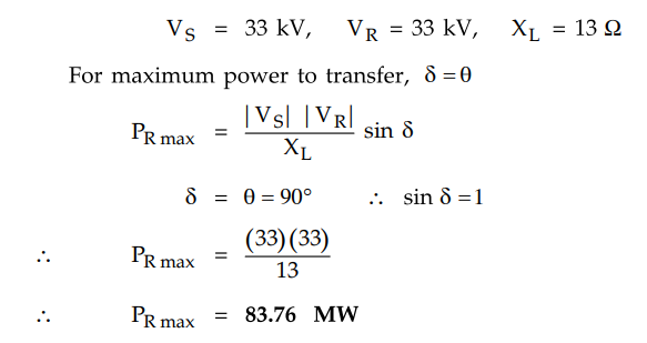
Example 2.19.1
A 3 phase overhead line has a reactance of 13 Ω per phase. If the voltage at
the two ends are maintained at 33 kV, calculate the maximum steady state power
that can be transmitted over the line.
AU: April-2000
Solution:
The given values are
Review Questions
1. Write a short note on power angle curve.
2. Write a note on stability of a power system.
AU: Dec.-13, Marks 6
Transmission and Distribution: Unit II: (a) Modelling and Performance of Transmission Lines : Tag: : Power Angle Diagram - Power System Stability
Related Topics
Related Subjects

Transmission and Distribution
EE3401 TD 4th Semester EEE Dept | 2021 Regulation | 4th Semester EEE Dept 2021 Regulation