Electrical Machines: Unit II: D.C. Generators
Practical Commutation
DC Generators
Key Point: The reversal of current is likely to take place in short interval when a coil is short circuited by a brush so that transfer of current from one direction to other is carried out without any sparking. This process is called commutation.
Practical
Commutation
AU: Dec.-07, 09, 12, 15, 16, 17,
May-03, 10
• The e.m.f. induced in each coil of armature is alternating in nature. If load is connected, the current flowing will also be alternating. But the flow of current in a d.c. generator must be unidirectional. This can be achieved by the use of commutator. When the armature conductors are under the influence of one pole they carry current in one direction whereas the current is reversed when the conductors are under the influence of other pole. This reversal of current takes place along the magnetic neutral axis.
Key Point:
The reversal of current is likely to take place in short interval when a coil
is short circuited by a brush so that transfer of current from one direction to
other is carried out without any sparking. This process is called commutation.
•
Thus a process by which current in the short circuited coil is reversed while
it crosses the MNA is called commutation. The time during which the coil
remains short circuited is known as commutation period. This period is
generally of the order of 0.0005 to 0.002 sec.
•
The commutation is said to be ideal when current changes from + I to zero and
zero to - I within the commutation period. The sparking is produced between the
commutator and brush if current is not reversed by that time. This will lead to
damage of commutator as well as brush. Hence for satisfactory operation of d.c.
machine proper commutation is required i.e. transfer of current must be without
sparking and losses and heating of brushes and the commutator.
•
Now we will see the process of commutation in detail with the help of the
figures. Let us assume that the armature winding is ring type and the width of
brush is equal to the width of one commutator segment and one mica insulation.
In this case only one coil is short circuited at a time at each of these
brushes whereas in actual practice width of brush is more than that of
commutator so that more than two coils are simultaneously short circuited at
each brush.
•
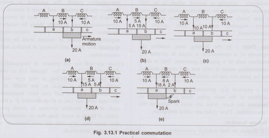
As shown in the Fig. 3.13.1 (a), coil B is about to be short circuited. The
brush is about to come in contact with commutator segment 'a'. Suppose that
each coil is carrying current of 10 A so that total brush current is 20 A as
every coil meeting at the brush supplies half the brush current independent of
lap or wave wound armature.
•
Before coil B is short circuited, it is belonging to the group of coils lying
left of the brush. It is carrying current 10 A from left to right.
• As seen from the Fig. 3.13.1 (b), coil B is entering short circuit period. The current in coil B has reduced from 10 A to 5 A as the other 5 A flows via segment 'a'. The total current is remaining same at 20 A. But area of contact of the brush is more with segment 'b' than with segment 'a'. Hence current of 15 A is from segment 'b' whereas 5 A from segment 'a'.
The coil B is in the middle of its short circuit period as shown in the Fig. 3.13.1 (c). The current in coil B is reduced to zero. The currents 10 A and 10 A pass to the brush directly from coils A and C. The total current is again 20 A and the contact area of brush with the segments 'a' and 'b' are equal.
• As shown in the Fig. 3.13.1 (d), the coil B is now under group of coils to the right of brush. The contact area of brush with segment 'b' is decreasing whereas with segment ‘a’ is increasing. Coil B is now carrying 5 A in other direction. Thus current of 15 A is passed via. segment 'a' to the brush while the other 5 A is supplied by coil C and passes from segment 'b' to brush. Again the total current is 20 A.
• If case of ideal commutation is assumed then current through coil will reverse at the end of commutation or short circuit period. But as shown in Fig. 3.13.1 (e) current flowing through coil B is only 8 A instead of 10 A. So the difference in coil currents i.e. 10 - 8 = 2 A jumps directly from segment 'b' to the brush through air and produces spark.
•
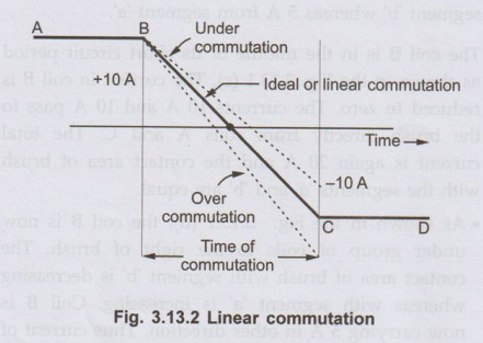
The variation in current during the process of commutation can be plotted with
respect to time as shown in the Fig. 3.13.2.
•
The current in the coil B is 10 A till commutation begins represented by
horizontal line AB. After finishing commutation the current is again 10 A but
in reverse direction represented by horizontal line CD. Thus current changes from
+10 A to 0 and then to -10 A. The way in which this current changes is
important. If current varies uniformly represented by straight line BC the
commutation is said to be linear commutation. But it is observed that the self
induced e.m.f. in the coil will try to maintain the current in the same
direction and will cause delay for commutation. The commutation in this case is
said to be retarded or under commutation. This is shown by the dotted part in
the Fig. 3.13.2 If reversal of current in the coil is faster than ideal or
linear commutation then also sparking may occur. The commutation in this case
is said to be over commutation or accelerated commutation.
•
Thus it can be seen that if reversal of current is retarded or accelerated then
value of current in the short circuited coil after the commutation period is
over is different than that when linear commutation occurs. This will cause
sparking at the brushes. This will lead to excessive wear and tear of
commutator and ultimately lead to burning of commutator. Hence it is desired
that the commutation must be as sparkless as possible.
•
Now Let us see that why there is delayed or accelerated commutation. The main
reason for non-linear commutation is the production of self induced e.m.f. in
the coil undergoing commutation as the coil has significant amount of self
inductance because it is embedded in the armature which is made up of high
permeability material. This self induced e.m.f. though small in magnitude
produces a large current through the coil whose resistance is small due to
short circuit.
1. Expression of Reactance Voltage
•
The e.m.f. induced in the coil undergoing commutation can be calculated as
follows.
Let
Wb = Brush width
Wm
= Width of mica insulation
V
= Peripheral velocity of commutator segment
•
The period of commutation is nothing but the time required by commutator to
move a distance equal to circumferential thickness of the brush minus the
thickness of one insulating plate.
•
If T is the time required for commutation then,
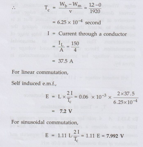
Tc
=Wb-Wm / V
•
Generally Wb and Wm are given interms of number of
segments. But if Wb is given in cm and commutator diameter D is given in cm
then v is to be calculated in cm/second as,
V = π Dc N/60 Cm/s
•
The total change in current during the process of commutation is 2I. Therefore
self induced or reactance voltage is given by,
•
Self induced voltage = Coefficient of self inductance × Rate of change of
current
Self
induced voltage = L × 2I / Tc ....(Linear commutation)
•
This self induced e.m.f. will oppose the change of direction of current. As
stated earlier this will cause sparking at the brushes since current in the
short circuited coil does not reach to its full value in the reversed direction
by the end of commutation. Thus to avoid sparking and short circuit of whole
machine due to arc producing around the commutator, commutation must be made
sparkless by using some methods.
•
With retarded communication, the current density is excessive at trailing edge
while it is small at leading edge. Whereas in accelerating commutation, the
current density is small at trailing edge and excessive at leading edge. This
indicates that it is desirable to retard the commutation during the initial
moments and to accelerate it at later stage of commutation. This is known as sinusoidal
commutation. Hence the self induced voltage or reactance voltage for sinusoidal
commutation is given by,
Self
induced voltage = 1.11 × L × 2I/ Tc...(Sinusoidal commutation)
L
= Coefficient of self inductance
Tc
= Time of commutation.
Ex 3.13.1 A 4 pole lap wound armature
running at 1800 r.p.m. delivers a current of 150 A and has 64 commutator
segments. The brush spans 1.2 segments and inductance of each armature coil is
0.06 mH.
Calculate the value of reactance
voltage assuming i) Linear commutation ii) Sinusoidal commutation. Neglect mica
thickness.
Sol.
The
given values are,
I
= 150 N = 1800 r.p.m. Wb = 1.2 segments
Wm
= 0 L = 0.06 mH 64 segments
There
are total 64 segments on the entire periphery. It is necessary to calculate the
peripheral seppd in segments/second as Wb is given in segments.
Now
the commutator speed is 1800 r.p.m. i.e.
ns
= 1800/60 = 30 r.p.s.
i.e.
revolution per second
And
in one revolution, 64 segments get covered. Hence
V
= Peripheral speed in segments/second
=
No.of revolutions per second × Total segments on commutator
=
30 × 64 = 1920 segments/second
Review Questions
1. Discuss in detail,
the phenomenon of commutation in d.c. machines.
AU May-03, 10,
Dec.-09, 12, 15, 16, 17, Marks 10
2. Explain the
following terms: Ideal commutation, over commutation, under commutation.
3. Explain under
commutation in D.C. machines.
AU: Dec.-07, Marks 4
Electrical Machines: Unit II: D.C. Generators : Tag: : DC Generators - Practical Commutation
Related Topics
Related Subjects

Electrical Machines I
EE3303 EM 1 3rd Semester EEE Dept | 2021 Regulation | 3rd Semester EEE Dept 2021 Regulation