Electrical Machines: Unit IV: Single Phase Transformer
Practical Transformer on No Load
Single Phase Transformer
• Actually in practical transformer iron core causes hysteresis and eddy current losses as it is subjected to alternating flux. While designing the transformer the efforts are made to keep these losses minimum by,
Practical
Transformer on No Load
AU: Dec.-06,14, May-08
•
Actually in practical transformer iron core causes hysteresis and eddy current
losses as it is subjected to alternating flux. While designing the transformer
the efforts are made to keep these losses minimum by,
1.
Using high grade material as silicon steel to bas reduce hysteresis loss.
2.
Manufacturing core in the form of laminations or stacks of thin laminations to
reduce eddy current loss.
•
Apart from this there are iron losses in the practical transformer. Practically
primary winding has certain resistance hence there are small primary copper
loss present.
•
Thus the primary current under no load condition has to supply the iron losses
i.e. hysteresis loss and eddy current loss and a small amount of primary copper
loss. This current is denoted as I0.
•
Now the no load input current I0 has two components:
1.
A purely reactive component Im called magnetising component of no
load current required to produce the flux. This is also called wattless
component.
2.
An active component Ic which supplies total losses under no load
condition called power component of no load current. This is also called
wattful component or core loss component of I0.
•
The total no load current I0 is the vector addition of Im
and Ic.
•
In practical transformer, due to winding resistance, no load current I0
is no longer at 90° with respect to V1. But it lags V1 by
angle ϕ0 which is less than 90°. Thus cos ϕ0 is called no
load power factor of practical transformer.
•
The phasor diagram is shown in the Fig. 6.7.1. It can be seen that the two
components of I0 are.

Im
= I0 Sin ϕ0 ............... (6.7.2)
•
This is magnetising component lagging V1 exactly by 90o.
Ic
= I0 cos ϕ0.................... (6.7.3)
• This is core loss component which is in
phase with V1.
The
magnitude of the no load current is given by,
I0
= √Im2+Ic2 ......................(6.7.4)
While
ϕ = no load primary power factor angle
•
The total power input on no load is denoted as W0 and is given by,
W0
= V1 I0 cos ϕ0 =V1 Ic ............(6.7.5)
•
It may be noted that the current I0 is very small, about 3 to 5 % of
the full load rated current. Hence the primary copper loss is negligibly small
hence Ic is called core loss or iron loss component. Hence power
input W0 on no load always represents the iron losses, as copper
loss is negligibly small. The iron losses are denoted as Pi and are
constant for all load conditions.
W0=
V1 I0 cos ϕ0 = Pi = Iron loss ......(6.7.6)
Ex. 6.7.1 The no load current of a
transformer is 10 A at a power factor of 0.25 lagging, when connected to 400 V,
50 Hz supply. Calculate,
a) Magnetising component of no load
current
b) Iron loss and
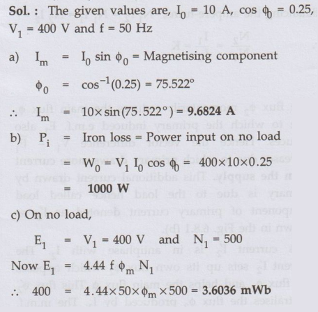 c) Maximum value
of flux in the core. Assume primary winding turns as 500.
c) Maximum value
of flux in the core. Assume primary winding turns as 500.
Sol. :
Review Question
1. Draw and explain
the no load phasor diagram of a single phase transformer. AU: Dec.-06,14,
May-08, Marks 8
Electrical Machines: Unit IV: Single Phase Transformer : Tag: : Single Phase Transformer - Practical Transformer on No Load
Related Topics
Related Subjects

Electrical Machines I
EE3303 EM 1 3rd Semester EEE Dept | 2021 Regulation | 3rd Semester EEE Dept 2021 Regulation