Electrical Machines: Unit II: D.C. Generators
Principle of Operation of a D.C. Generator
Such an induced e.m.f. which is due to physical movement of coil or conductor with respect to flux or movement of flux with respect to coil or conductor is called dynamically induced e.m.f.
Principle
of Operation of a D.C.Generator
AU: Dec.-16, May-10,15
•
All the generators work on a principle of dynamically induced e.m.f. This
principle is nothing but the Faraday's law of electromagnetic induction. It
states that, 'Whenever the number of magnetic lines of force i.e. flux linking
with a conductor or a coil changes, an electromotive force is set up in that
conductor or coil.' The change in flux associated with the conductor can exist
only when there exists a relative motion between a conductor and the flux. The
relative motion can be achieved by rotating conductor with respect to flux or
by rotating flux with respect to a conductor. So a voltage gets generated in a
conductor, as long as there exists a relative motion between conductor and the
flux.
•
Such an induced e.m.f. which is due to physical movement of coil or conductor
with respect to flux or movement of flux with respect to coil or conductor is
called dynamically induced e.m.f.
Key Point :
So a generating action requires following basic components to exist,
i)
The conductor or a coil ii) The flux iii) The relative motion between conductor
and flux.
•
In a practical generator, the conductors are rotated to cut the magnetic flux,
keeping flux stationary. To have a large voltage as the output, the number of
conductors are connected together in a specific manner, to form a winding. This
winding is called armature winding of a d.c. machine. The part on which this
winding is kept is called armature of a d.c. machine. To have the rotation of
conductors, the conductors placed on the armature are rotated with the help of
some external device. Such an external device is called a prime mover. The
commonly used prime movers are diesel engines, steam engines, steam turbines,
water turbines etc. The necessary magnetic flux is produced by current carrying
winding which is called field winding. The direction of the induced e.m.f. can
be obtained by using Fleming's right hand rule.
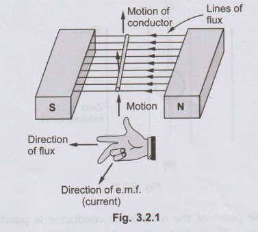
1. Fleming's Right Hand Rule
•
If three fingers of a right hand, namely thumb, index finger and middle finger
are outstretched so that everyone of them is at right angles with the remaining
two and if in this position index finger is made to point in the direction of
lines of flux, thumb in the direction of the relative motion of the conductor
with respect to flux then the outstretched middle finger gives the direction of
the e.m.f. induced in the conductor. Visually the rule can be represented as
shown in the Fig. 3.2.1.
•
This rule mainly gives direction of current which induced e.m.f. in conductor
will set up when closed path is provided to it.
•
The magnitude of the induced e.m.f. is given by,
E
= B × l × v
where
l = Active length of conductor in m
v = Relative velocity component of
conductor
in m/s in the direction
perpendicular
to direction of the flux.
•
The active length means the length of conductor which is under the influence of
magnetic field. In all the cases above, direction of motion of conductor is
perpendicular to the plane of the flux.
•
But if it is not perpendicular then the component of velocity which is
perpendicular to the plane of the flux, is only responsible for inducing e.m.f.
in the conductor. This is shown in the Fig. 3.2.2 (a). In this Fig. 3.2.2 (a),
though the velocity is v, its component v' which is perpendicular to the flux
lines is only responsible for the induced e.m.f.
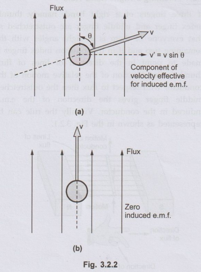
• If the plane of the rotation oof conductor is parallel to the plane of the flux, there will not be any cutting of flux and hence there cannot be any induced e.m.f. in the conductor. This is shown in the Fig. 3.2.2(b)
Key Point:
So to have an induced e.m.f. in the conductor not only the relative motion
between the conductor and the flux is necessary but plane of rotation and plane
of flux should not be parallel to each other.
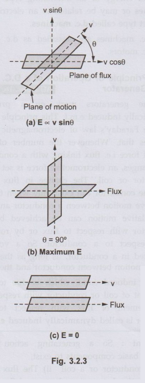
• If angle between the plane of rotation and the plane of the flux is '0' as measured from the axis of the plane of flux then the induced e.m.f. is given by,
E = Bl (v sin θ) volts
•
where v sin θ is the component of velocity which is perpendicular to the plane
of flux and hence responsible for the induced e.m.f. This is shown in the Fig.
3.2.3.
•
From the equation of the induced e.m.f., it can be seen that the basic nature
of the induced e.m.f. in a d.c. generator is purely sinusoidal i.e.
alternating. To have d.c. voltage, a device is used in a d.c. generator to
convert the alternating e.m.f. to unidirectional e.m.f. This device is called commutator.
Review Questions
1. Explain the
principle of operation of a d.c. not generator?
AU: Dec.-16, Marks 8
2. Discuss the basic
concepts of e.m.f. generation in a d.c. machines in detail.
AU May-10, Marks 8
Electrical Machines: Unit II: D.C. Generators : Tag: : - Principle of Operation of a D.C. Generator
Related Topics
Related Subjects

Electrical Machines I
EE3303 EM 1 3rd Semester EEE Dept | 2021 Regulation | 3rd Semester EEE Dept 2021 Regulation