Microprocessors and Microcontrollers: Unit IV: (d) Serial Data Transfer (USART) 8251
Programming 8251A
Serial Data Transfer (USART) 8251
Review Question : 1. Explain the operation and programming of 8251 USART in detail.
Programming 8251A
To
implement serial communication the CPU must inform the 8251A all details such
as mode, baud rate (in case of asynchronous mode), stop bits, parity etc.
Therefore, prior to data transfer, a set of control words must be loaded into
the mode instruction and control instruction registers of 8251A.
Example
Write the sequence of instructions required to initialize 8251A at address
80H and 81H for the configuration given below
i)
Character length - 6 bits
ii)
Parity even
iii)
Stop bit 1
iv)
Baud rate 64 X
v)
DTR and RTS asserted
vi)
Error flag reset
vii)
Transmitter enable
Solution
:
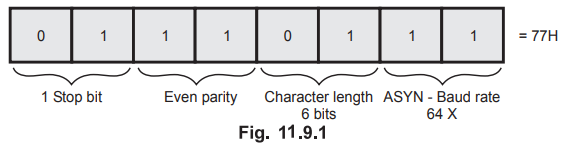
In the example, number of stop bits and baud rate is specified, therefore, it
is necessary to initialize 8251A in the asynchronous mode.
Mode
word for given specification is as follows :
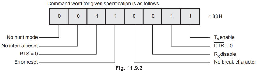
Command word for given specification is as follows :
Program
:
MVI
A, 00H
OUT
81H ; Dummy mode word
OUT
81H
OUT
81H
MVI
A, 40 H ; Reset command word
OUT
81H ; Reset 8251A
MVI
A, 77H ; Mode Word initialization
OUT
81H
MVI
A, 33 H ; Command word initialization
OUT
81H
Note
Before
initialization of the 8251A, the dummy mode word and the reset command are sent
to the control register. Initially control register may have any random word;
therefore, it is a good practice to reset the 8251A. However, it expects the
instruction as a mode word followed by the command word. Therefore, the reset
command is sent after sending three dummy mode words, which are recommended to
avoid problems when it is turned on.
Lab Experiment 11.9.1 ; Transmit
message using 8251.
Statement :
Draw interfacing diagram and write a assembly program to transmit a message
from an 8085 to a CRT terminal for the following requirements.
i)
A message of 50 characters is stored as ASCII characters (without parity) in
memory locations starting at 2200H.
ii)
Baud rate × 16
iii)
Stop bits 2
Solution
:
CRT terminal uses normal RS 232C standard serial communication interface.
Therefore to transmit data to CRT it is necessary to have RS 232C interface at
the sending end. Fig. 11.9.3 shows the interfacing of 8251 with RS 232C to
8085.
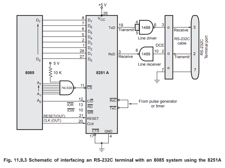
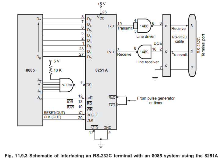
As
shown in the Fig. 11.9.3 three RS-232C signals (TxD, RXD are Ground) are used
for serial communication between the CRT terminal and the 8085 system. Line
drivers and receivers are used to transfer logic levels from TTL logic to
RS-232C logic. For RS-232C the voltage level +3 V to +15 V is defined as logic
0 and voltage level from -3 V to -15 V is defined as logic 1. The line driver,
MC 1488, converts logic 1 of TTL to approximately -9 V and logic 0 of TTL to
approximately +9 V. These levels at the receiving end are again converted by
the line receiver, MC1489, into TTL compatible logic.
I/O Map:
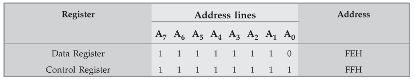
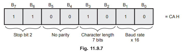
Mode word necessary for the given specification is as follows :
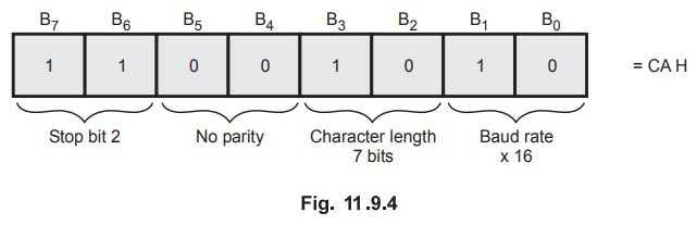
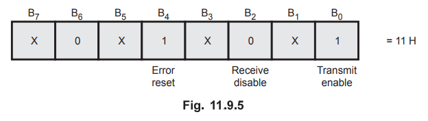
Command
word necessary for the given specification is as follows :
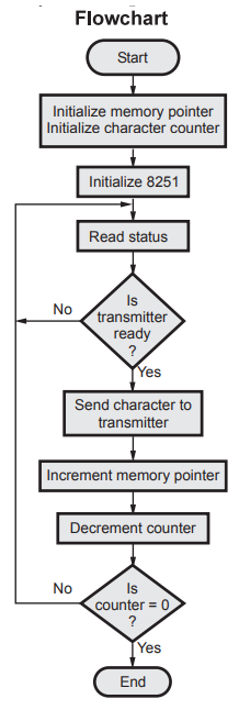
To
transmit characters on the TxD line it is necessary for 8085 check whether
transmitter is ready or not. This can be checked by reading status word as
shown in the Fig. 11.9.6.
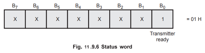
If
bit 0 of the status word is logic '1' then transmitter is ready to accept the
character.
Program
:
LXI
H, 2200H ; Initialize memory pointer to
;
point the message
MVI
C, 32H ; Initialize counter to send
;
50 characters
MVI
A, 00H
OUT
FFH
OUT
FFH ; Dummy mode word
OUT
FFH
MVI
A, 40H ; Reset command word
OUT
FFH ; Reset 8251A
MVI
A, CAH ; Mode word initialization
OUT
FFH
MVI
A, 11H ; Command word initialization
OUT
FFH
CHECK
: IN FFH
ANI
01H ; Check TxRDY
JZ
CHECK ; Is TxRDY 1 ? if not, check
;
again
MOV
A, M ; Get the character in
;
accumulator
OUT
FEH ; Send character to the transmitter
INX
H ; Increment memory pointer
DCR
C ; Decrement counter
JNZ
CHECK ; if not zero, send next character
HLT
; Stop program execution
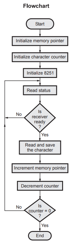
Lab Experiment 11.9.2 : Receive message
using 8251.
Statement :
For the interfacing in lab experiment 66, write an assembly language program to
receiver 25 bytes from the CRT terminal.
Solution
: Mode
word necessary for the given specification is as follows :
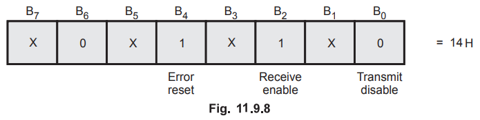
Command word necessary for the given
specification is as follows :
To
receive character from RxD line it is necessary for 8085 to check whether
receiver is ready to give data or not. This can be checked by reading status
word as shown in the Fig. 11.9.9.
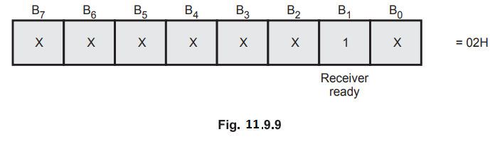
If
bit 1 of the status word is logic '1' then receiver is ready to give the
character.
Program
:
LXI
H, 2300 H ; Initialize memory pointer
MVI
C, FFH ; Initialize counter to accept 25
;
characters
MVI
A, 00H
OUT
FFH ; Dummy mode word
OUT
FFH
MVI
A, 40 H ; Reset command word
OUT
FFH ; Reset 8251A
MVI
A, CAH ; Mode word initialization
OUT
FFH
MVI
A, 14H ; Command word initialization
OUT
FFH
CHECK
: IN FFH
ANI
02H ; Check RxRDY
JZ
CHECK ; Is RxRDY 1 ? If not, check
;
again
IN
FEH ; Get the character
MOV
M, A ; save the character
INX
H ; Increment memory pointer
DCR
C ; Increment memory pointer
OUT
FEH ; Send character to the
;
transmitter
JNZ
CHECK ; If not zero, accept next
;
character
HLT
; Stop program execution
Review Question
1. Explain the operation and programming of 8251 USART in detail.
Microprocessors and Microcontrollers: Unit IV: (d) Serial Data Transfer (USART) 8251 : Tag: : Serial Data Transfer (USART) 8251 - Programming 8251A