Microprocessors and Microcontrollers: Unit IV: (b) Programmable Interrupt Controller (PIC) - 8259
Programming the 8259A
Microprocessors and Microcontrollers
The 8259A requires two types of command words. Initialization Command Words (ICWs) and Operational Command Words (OCWs). The 8259A can be initialized with four ICWs; the first two are compulsory, and the other two are optional based on the modes being used.
Programming the 8259A
The
8259A requires two types of command words. Initialization Command Words (ICWs)
and Operational Command Words (OCWs). The 8259A can be initialized with four
ICWs; the first two are compulsory, and the other two are optional based on the
modes being used. These words must be issued in a given sequence. After
initialization, the 8259A can be set up to operate in various modes by using
three different OCWs; however, they are not necessary to be issued in a
specific sequence. Refer Fig. 9.6.1 for initialization flowchart.

Initialization
Command Word 1 (ICW1)
Fig.
9.6.2 shows the Initialization Command Word 1(ICW1). A write command issued to
the 8259 with A0 = 0 and D4 = 1 is interpreted as ICW1,
which starts the initialization sequence. It specifies,
1.
Single or multiple 8259As in the system.
2.
4 or 8 bit interval between the interrupt vector locations.
3.
The address bits A7 - A5 of the CALL instruction. (3 bits of lower byte address
of CALL are given by user, rest bits are inserted by 8259A).
4.
Edge triggered or level triggered interrupts.
5.
ICW4 is needed or not.

Initialization Command Word 2 (ICW2)
Fig.
9.6.3 shows the Initialization Command Word 2 (ICW2).
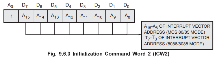
A
write command following ICW1, with A0 = 1 is interpreted as ICW2.
This is used to load the high order byte of the interrupt vector address of all
the interrupts.
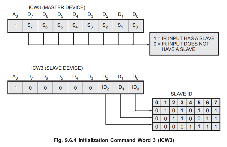
Initialization
Command Word 3 (ICW3) : ICW3 is required only if there is
more than one 8259 in the system and if they are cascaded. An ICW3 operation
loads a slave register in the 8259. The format of the byte to be loaded as an
ICW3 for a master 8259 or a slave is shown in the Fig. 9.6.4. For master, each
bit in ICW3 is used to specify whether it has a slave 8259 attached to it on
its corresponding IR (Interrupt Request) input. For slave, bits D0 -
D2 of ICW3 are used to assign a slave identification code (slave ID)
to the 8259.
Initialization
Command Word 4 (ICW4) : It is loaded only if the D0
bit of ICW1 is set. The format of ICW4 is shown in Fig. 9.6.5.
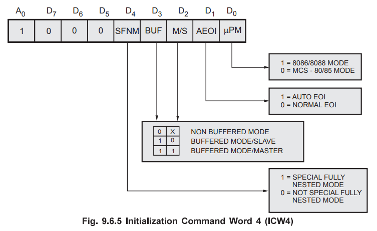
It
specifies,
1.
Whether to use special fully nested mode or non special fully nested mode.
2.
Whether to use buffered mode or non buffered mode.
3.
Whether to use Automatic EOI or Normal EOI.
4.
MPU used, 8086/8088 or 8085.
Operation
Command Words (OCWs) : After initialisation, the 8259 is
ready to process interrupt requests. However, during operation, it might be
necessary to change the mode of processing the interrupts. Operation Command
Words (OCWs) are used for this purpose. They may be loaded anytime after the
initialisation of 8259 to dynamically alter the priority modes.
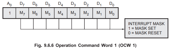
Operation
Command Word 1 (OCW 1) : A Write command to the 8259 with
Ao = 1 (after ICW2) is interpreted as OCW1. OCW1 is used for enabling or
disabling the recognition of specific interrupt requests by programming the
IMR.
M
= 1 indicates that the interrupt is to be masked, and M = 0 indicates that it
is to be unmasked as shown in Fig. 9.6.6.
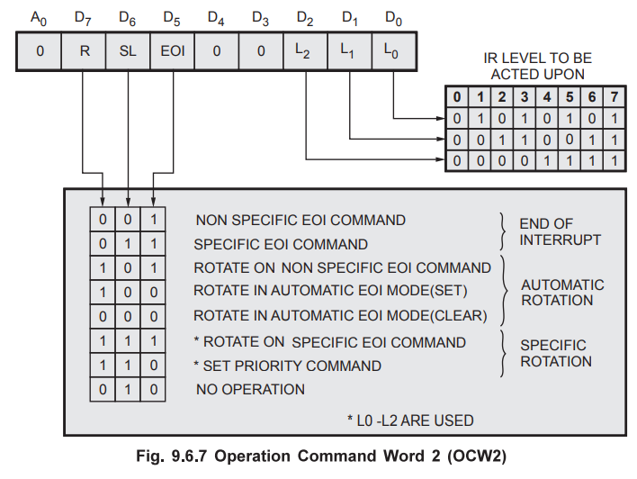
Operation
Command Word 2 (0CW2) : A Write command with A0
= 1 and D4 D3 = 00 is interpreted as OCW2. The R
(Rotate), SL (Select-Level), EOI bits control the Rotate and End of Interrupt
Modes and combinations of the two. Fig. 9.6.7 shows the Operation Command Word
format. L2 – L0 are used to specify the interrupt level
to be acted upon when the SL bit is active.
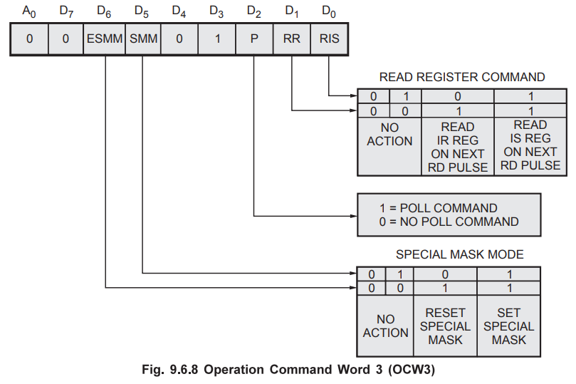
Operation
Command Word 3 (OCW3) : OCW3 is used to read the status of
the registers, and to set or reset the Special Mask and Polled modes. Fig.
9.6.8 shows format of operation command word 3.
8259
Status Read Operations : The status of the Interrupt
Request Register, the Interrupt-Service Register, and the Interrupt Mask
Register of the 8259 may be read by issuing appropriate Read commands as
described further.
IRR
Status Read : An OCW3 with RR (Read Register) = 1 and
RIS (Read ISR) = 0 set up the 8259 for a status read of the Interrupt Request
Register.
When
the 8259 is not in the Polled mode, after it is set up for an IRR status read
operation, all Read commands with A0 = 1 cause the 8259 to send the
IRR status word.
ISR
Status Read : An OCW3 with RR = 1 and ISR = 1 sets up
the 8259 for a status read of the Interrupt-Service Register. A subsequent read
command issued to the 8259 will cause the 8259 to send the contents of the ISR
onto the data bus.
IMR
Status Read : A Read command issued to the 8259 with
A0 = 1 (with ![]() = 0,
= 0, ![]() = 0 ) causes the 8259 to put the contents of the
Interrupt Mask Register on the data bus. OCW3 is not required for a status read
of the IMR.
= 0 ) causes the 8259 to put the contents of the
Interrupt Mask Register on the data bus. OCW3 is not required for a status read
of the IMR.
As
described earlier, the sequence shown in flowchart must be followed to
initialize 8259A. According to this flowchart, an ICW1 and an ICW2 must be sent
to any 8259A in the system. If the system has any slave 8259As (cascade mode),
then an ICW3 must be sent to the master, and a different ICW3 must be sent to
the slave. If the system is an 8086, or if you want to specify certain special
conditions, then you have to send an ICW4 to the master and to each slave. To
have better understanding the initialisation sequences for different
specifications are given in the next section.
Note
It is assumed that A0 of the system bus is connected to the A0
of the 8259A. So the internal addresses are correspond to 0 and 1. It is also
assumed that the base address of the device is 40H. So the two system addresses
for the 8259A are 40H and 41H.
Example
9.6.1 Write the initialization instructions for 8259A
interrupt controller to meet the following specifications :
1.
Edge triggered, single and ICW4 are not needed.
2.
Mask interrupts IR2 and IR3.
3.
Interrupt vector address for IR0 is 6280H and
4.
Call address intervals are four bytes.
Solution
:
ICW1
ICW2
In
an 8085 system, ICW2 is used to tell the 8259A the higher byte of the interrupt
service routine address to be sent in response to an interrupt signal on the
IR0 input.

ICW3
Since
we are not using a slave in our example, we don't need to send an ICW3.
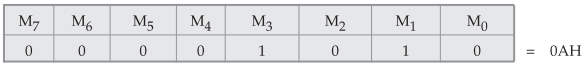
OCW1
An
OCW1 must be sent to an 8259A to unmask any IR inputs. For our example we want
to mask IR1 and IR3, so we put 1s in these two bits and 0s
in the rest of the bits.
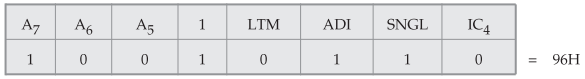
Program :
MVI
A, 96H ; Edge triggered, single, interval 4, ICW4 not needed
OUT
40H ; Send ICW1
MVI
A, 62H ; Higher byte of ISR.
OUT
41H ; Send ICW2
MVI
A, 0AH ; OCW1 to mask IR1 and IR3
OUT
41H ; Send OCW1
Example
9.6.2 Write the initialization instructions for master
and slave configuration to meet the following specifications :
1.
The INTR of slave is routed through IR2 of the master 8259A to the 8085.
2.
Master and slave are both level triggered.
3.
Master Interrupt vector address for IR0 is 6280H.
4.
Slave Interrupt vector address for IR0 is 7280H.
5.
Modes : automatic rotation and auto end of interrupt.
6.
Addresses of the master are 40H and 41H and the slave are 80H and 81H.
7.
Buffers are not used.
Solution
:
Initialization
Command Words for Master
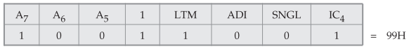
ICW1
(master)
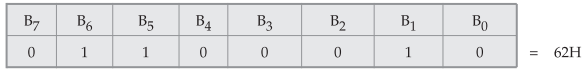
ICW2
(master)
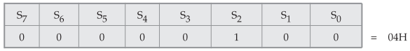
ICW3
(master)
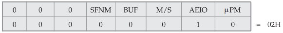
ICW4
(master)
Program
:
MVI
A,99H ; level triggered, cascaded, ICW4 needed
OUT
40H ; send ICW1 (master)
MVI
A,62H ; Higher byte of ISR
OUT
41H ; send ICW2 (master)
MVI
A,04H ; slave at IR2
OUT
42H ; send ICW3 (master)
MVI
A,02H ; ICW4, 8085 mode, and set AEOI
OUT
41H ; send ICW4 (master)
MVI
A,99H ; level triggered, cascaded, ICW4 needed
OUT
80H ; send ICW1 (slave)
MVI
A,72H ; Higher byte of ISR
OUT
81H ; send ICW2 (slave)
MVI
A,02H ; ID for slave connected to IR2
OUT
81H ; send ICW3 (slave)
MVI
A,02H ; ICW4, 8085 mode
OUT
81H ; send ICW4
MVI
A,80H ; OCW2 (rotate in auto EOI mode set command)
OUT
80H ; send OCW2 (slave)
Review Question
1. Explain the ICWs and OCJNs with the help of example.
Microprocessors and Microcontrollers: Unit IV: (b) Programmable Interrupt Controller (PIC) - 8259 : Tag: : Microprocessors and Microcontrollers - Programming the 8259A