Linear Integrated Circuits: Unit V: Application ICs
Protection Circuit in Regulators
Operating working principle, Features, Block Diagram, Circuits Diagram, Disadvantage, Solved Example Problems
The series regulator using transistors has no short circuit protection. If the load terminals are shorted accidently then,
Protection Circuit in Regulators
The
series regulator using transistors has no short circuit protection. If the load
terminals are shorted accidently then,
1.
Large amount of load current will flow.
2.
The pass transistor Q1 will get destroyed.
3.
The diodes used in unregulated power supply, supplying the input voltage Vin
to regulator circuit may get destroyed.
To
avoid all such possibilities some sort of current limiting must be provided to
the series regulator.
The
various protection circuits used for the series voltage regulators are,
1.
Constant current limiting (Short circuit protection).
2.
Fold back current limiting.
3.
Overvoltage protection.
4.
Thermal shutdown.
1. Constant Current Limiting Circuit
A
block of series regulation using simple current limiting circuit is shown in
the Fig. 5.9.1. It is also called short circuit protection circuit as it
provides protection against short circuiting. The resistance R4 is
added m series with the pass transistor Q1 and the load which is
called current sensing resistor.

The drop across the current sensing resistance R4 is applied to the base-emitter of Q3. Under normal working condition and rated load current, this drop is insufficient to turn on the transistor Q3 and hence pass transistor Q1 continues to supply the rated load current.
When
current increases due to over loading or short circuit conditions then drop
across R4 increases more than 0.6 V. The 0.6 V is sufficient to turn
on the transistor Q3. The collector current of Q3 flows
through R3 and decreases the base voltage of Q1. This
decreases the load voltage. This decrease in output voltage prevents the large
load current.
The
value of R4 can be selected to adjust the rated current of the
circuit. As drop across R4 should be less than 0.6 V under normal
working condition, for rated current of 1 A, R4 can be selected as
0.7 9. For a rated current of 7 A, R4 must be selected as 0.1 2 and
so on.
Let
us study the variation of load current against load voltage with simple current
limiting.
When
R1 = ∞ i.e. output terminals open, the output voltage is Vo
current is zero.
When
load increases, the load resistance decreases and the load current increases.
The load current can increase till the drop across R4 is not equal
to 0.6 V. This load resistance at which drop across R4 is 0.6 V is
say Rmin. When load current further increases and R1 becomes zero
(short circuit), the load voltage decreases and the load current gets maintained
at a value less than rated current. After RL = Rmin the
regulation is lost and load voltage decreases as RL decreases. This
is shown in the 5.9.2.

Let
ISL = Load current when load terminals shorted.
In
such a case, drop across R4 is equal to VBE to turn on
the transistor Q3.
VBE
= ISL R4
ISL = VBE / R4 ... (5.9.1)
The minimum load resistance Rmin below which regulation is lost can be calculated as,
Rmin
= Vreg / ISL ... (5.9.2)
The
practical value of Rmin will be slightly greater or less than this.
2. Disadvantage of Simple Current Limiting
The
disadvantage of constant current limiting is relatively large power dissipation
in the series pass transistor when load terminals are shorted. Thus a large
power rating transistor is required.
The
power dissipation in the series pass transistor is given by,
PD
= (Vin - VBE) ISL ...(5.9.3)
where
VBE = Base-emitter voltage of Q1
The
circuit which is used in practice which eliminates the disadvantage of simple
current limiting is called foldback current limiting circuit.
Such
protection is provided in IC 723 with the help of resistance RSC
connected to CL (current limiting) pin. The drop across RSC is
applied across pins CL and CS. When this voltage becomes more than 0.6 V, it
turns on internal current limiting transistor Q3. The calculations
of RSC for IC 723 are discussed earlier while discussing the applications of IC
723.
3. Foldback Current Limiting
The
disadvantage of constant current limit is relatively large power dissipation in
the series pass transistor when the load terminals are shorted. Thus a large
power rating transistor is required. The foldback limiting technique allows us
to provide the necessary load current at rated voltage but reducing the short
circuit current. Thus the series pass transistor gets utilised efficiently. The
basic circuit for foldback limiting is shown in the Fig. 5.9.3.

All
the voltages are measured with respect to a common point.
Let
the voltage at point A be VA and the current flowing through R4
is almost IL.
VA
= IL R4 + Vo ...
(5.9.4)
Neglecting
the base current of Q3, the cmrent flowing through R5 and
R6 is same as I = VA / R5 + R6 ...
(5.9.5)
Hence
the voltage at the base of Q3 is the voltage across R6

Thus
if the output terminals are shorted, the output voltage Vo reduce to
zero.
Hence
we get from the equation (5.9.9)

The
rated load current IL is also called Iknee known as knee current.
It
can be observed from the equation (5.9.11) that the rated load current is more
than the short circuit current.
Key
Point Thus when the output terminals are shorted, the
current decreases rather than increasing. Thus the series pass transistor Q1
gets protected automatically.
The
ratio of rated load current and the short circuit current can be adjusted by
selecting proper value of k. Typically k is selected to produce a maximum load
current of 2 to 3 times the short circuit load current. The foldback
characteristics which is the graph of the load voltage against load current is
shown in the Fig. 5.9.4.
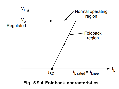
As
seen from the characteristics, beyond the rated value, if the load increases,
the voltage folds backward and finally becomes zero at Isc which is less than
the rated load current. Hence the protection circuit is called foldback
protection circuit.
The
foldback current limiting circuit design with IC 723 is explained in the
example below :
Example
5.9.1 Design a regulator using IC 723, to have Vo
= 6V and the load current of 1 A. Use the foldback protection to get Isc
of 250 mA.
Solution
:
It is a low voltage less than 7 V and high current more than 150 mA, regulator.
The circuit is shown in the Fig. 5.9.5.

Now
to calculate foldback circuit components R3, R4 and RSC.

Review Questions
1. Explain the use of
current limiting technique.
Dec.-04, 05, 06, 10, May-07, Marks 4
2. Briefly explain protection
circuits in voltage regulators.
Dec.-08, 09, Marks 8
3. Explain fold back
characteristic of 723 IC regulator.
Dec.-15, Marks 8
Linear Integrated Circuits: Unit V: Application ICs : Tag: : Operating working principle, Features, Block Diagram, Circuits Diagram, Disadvantage, Solved Example Problems - Protection Circuit in Regulators
Related Topics
Related Subjects

Linear Integrated Circuits
EE3402 Lic Operational Amplifiers 4th Semester EEE Dept | 2021 Regulation | 4th Semester EEE Dept 2021 Regulation