Basic Civil & Mechanical Engineering: UNIT IV: c. Steam Turbines
Reaction Turbine
Layout Diagram, Working Principle, Construction
Reaction is the force obtained on a body when a fluid leaves the body with a higher relative velocity. Examples: Lawn (Water) sprinkler, Recoil of a gun, Jet plane, etc.
REACTION TURBINE
Principle
Reaction
is the force obtained on a body when a fluid leaves the body with a higher
relative velocity.
Examples:
Lawn (Water) sprinkler, Recoil of a gun, Jet plane, etc.
In
Fig. 6(i), in the lawn sprinkler, water under pressure flows into the
sprinkler. The sprinkler rotates in the direction shown, due to the reaction of
the high velocity water jet.
See
Fig. 6(ii). Assume that high pressure high temperature steam from the boiler is
sent to a hollow cylindrical rotor.
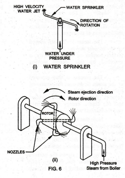
The
rotor has a few openings arranged radially through tubes. The ends of the tubes
are shaped as Nozzles. Steam expands as it passes through the nozzleş. .
This
expansion of steam causes a backward thrust on the nozzles. This backward
thrust is known as Reaction. Due to this reaction, the rotor will rotate in a
direction opposite to the direction of steam flow.
1. PARSON'S REACTION TURBINE
Pure
reaction turbine is never used in actual practice. In the actual reaction
turbine, power is obtained by the impulsive force of incoming steam and
reactive force of outgoing steam.
Descriptions
See
Fig. 7(i). C.A. Parson has built a Reaction Turbine with three stages. It
consists of a wheel or rotor and casing, both are of varying diameters. Equal
number of fixed and moving blades are attached alternately to the casing and
the wheel.
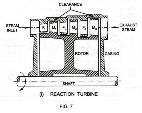
The
moving and fixed blades are not symmetrical in shape and are also curved in the
opposite direction.
The
shape of the moving blades is so designed to have the reactive force, when the
jet of steam is leaving the blades. Also, there will be some pressure drop in
the moving blades.
Fixed
blades are designed in such a way that the passages between them act as nozzles.
Hence, the velocity increases with the decrease of pressure.
Working
Steam
passes over the first fixed blade F1. The fixed blade changes the
direction of steam and at the same time, allows it to expand to a higher
velocity, with decrease of pressure.
Then,
the steam passes over the first moving blade M1. The moving blade
converts the kinetic energy into mechanical work with decrease of velocity.
But, at the same time, the steam expands as it flows over the moving blade and
there is a fall of pressure. This produces a reaction on the blade by the
expanding steam.
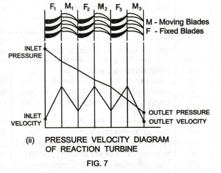
Thus,
in the reaction turbine, the steam expands both in fixed and moving blades
continuously as steam passes over them. So, the pressure drop occurs gradually
and continuously over both fixed and moving blades.
Fig.
7(ii) shows the Pressure Velocity Diagram of Parson's Reaction Turbine.
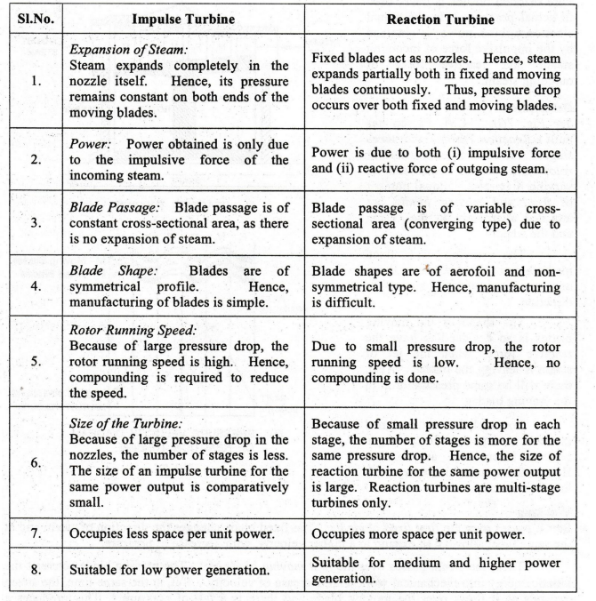
2. COMPARISON OF IMPULSE AND REACTION TURBINES
Basic Civil & Mechanical Engineering: UNIT IV: c. Steam Turbines : Tag: : Layout Diagram, Working Principle, Construction - Reaction Turbine
Related Topics
Related Subjects

Basic Civil and Mechanical Engineering
BE3255 2nd Semester 2021 Regulation | 2nd Semester EEE Dept 2021 Regulation